
Motor assembly sensor capture systems and methods

a sensor and motor assembly technology, applied in the field of encoder sensor systems and methods, can solve the problems of user-patient trauma of manual needle insertion into the patient-user

Active Publication Date: 2014-03-18
MEDTRONIC MIMIMED INC
View PDF5 Cites 235 Cited by
  • Summary
  • Abstract
  • Description
  • Claims
  • Application Information

AI Technical Summary

Benefits of technology

The sensor system described in this patent includes a drive shaft, an engagement member, a motor, a detectable feature, and at least one sensor. The engagement member is supported on the drive shaft and the motor is configured to drive the drive shaft and engagement member. The detectable feature is a rotary member that changes state when the drive shaft moves. The at least one sensor is positioned to detect the state of the detectable feature. The system may also include a housing to align the sensors and a shield to prevent light interference. The technical effects of this system include improved accuracy and reliability in detecting the state of the detectable feature and improved alignment of the sensors.

Problems solved by technology

In contexts in which the hollow tubing is connected to the patient-user through a hollow needle that pierces skin of the user-patient, a manual insertion of the needle into the patient-user can be somewhat traumatic to the user-patient.

Method used


Image

  • Motor assembly sensor capture systems and methods
  • Motor assembly sensor capture systems and methods
  • Motor assembly sensor capture systems and methods

Examples


Embodiment Construction

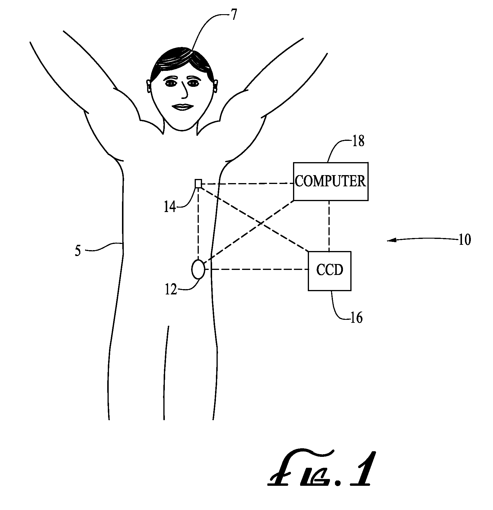
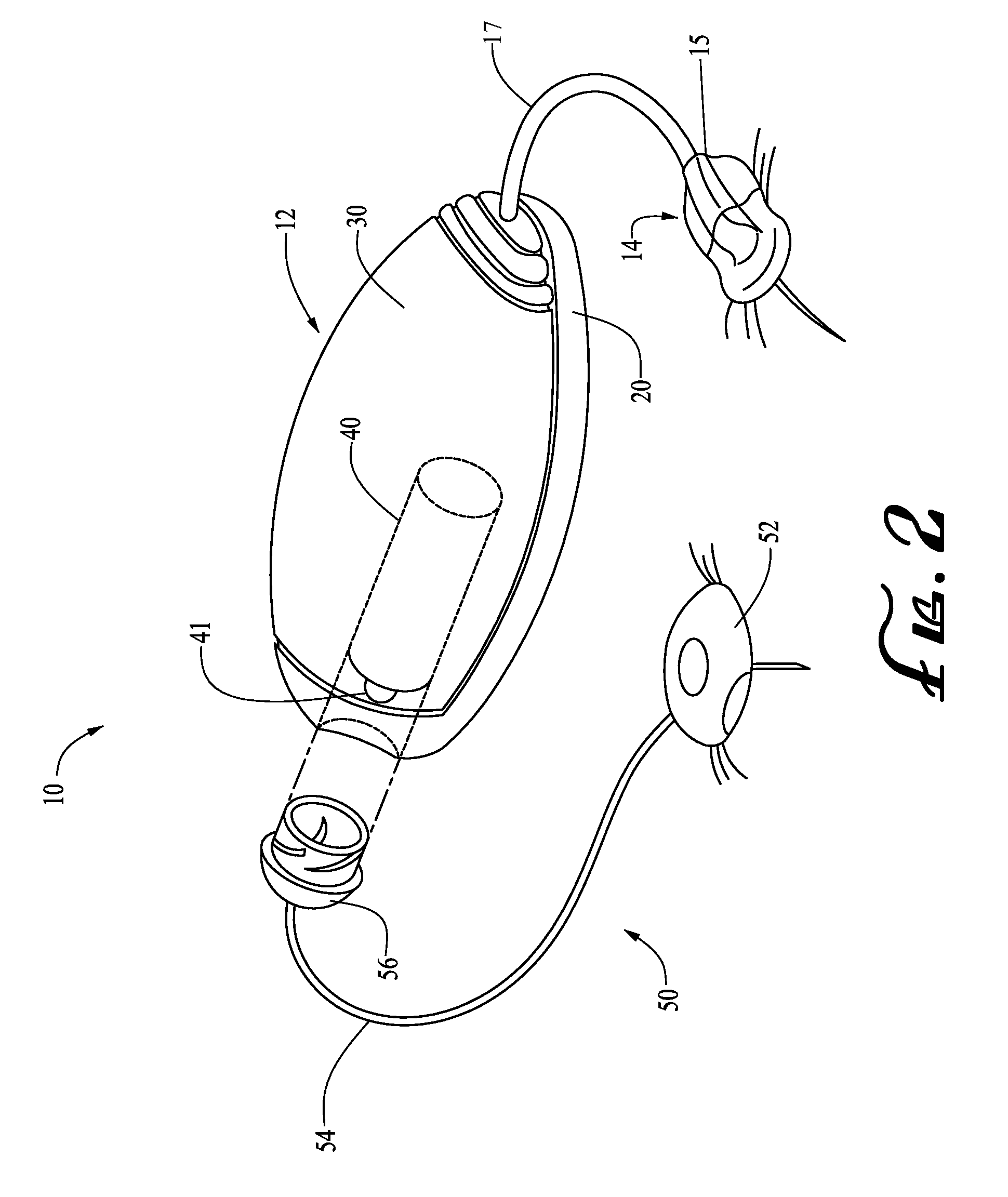
[0046]FIG. 1 illustrates a generalized representation of a system 10 in accordance with an embodiment of the present invention. The system 10 may include a delivery device 12. The system 10 may further include a sensing device 14, a command control device (CCD) 16, and a computer 18. In various embodiments, the delivery device 12 and the sensing device 14 may be secured at desired locations on the body 5 of a patient or user-patient 7. The locations at which the delivery device 12 and the sensing device 14 are secured to the body 5 of the user-patient 7 in FIG. 1 are provided only as representative, non-limiting, examples.

[0047]The system 10, the delivery device 12, the sensing device 14, the CCD 16, and computer 18 may be similar to those described in the following U.S. patent applications that were assigned to the assignee of the present invention, where each of following patent applications is incorporated herein by reference in its entirety: (i) U.S. patent application Ser. No. ...


PUM

PropertyMeasurementUnit
movementaaaaaaaaaa
flexibleaaaaaaaaaa
durableaaaaaaaaaa

Abstract

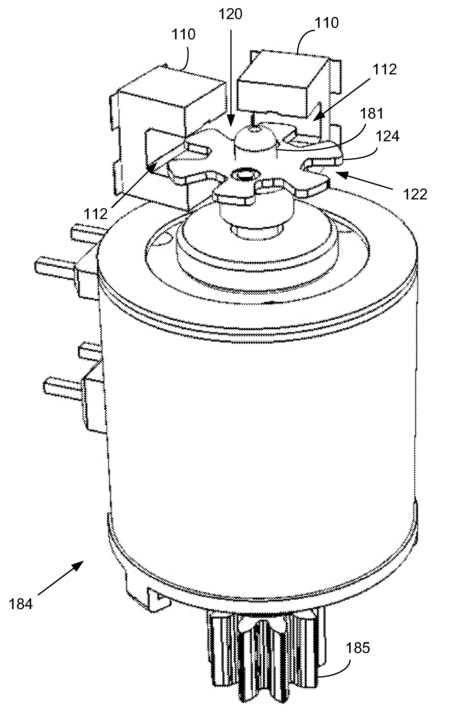
A motor may be configured to drive a drive shaft and an engagement member supported on the drive shaft. A detectable feature comprising a rotary member may be supported on the drive shaft such that movement of the drive shaft by the motor changes a state of the detectable feature. At least one sensor may be arranged to detect the state of the detectable feature. Circuitry may be configured to provide a signal in response to a change in the state of the detectable feature detected by the at least one sensor.

Description

CROSS-REFERENCE TO RELATED PATENT APPLICATIONS[0001]This application claims priority from Provisional application U.S. Application 61 / 317,200, filed Mar. 24, 2010, incorporated herein by reference in its entirety.BACKGROUND[0002]1. Field of the Invention[0003]Embodiments of the present invention generally relate to encoder sensor systems and methods, and, in specific embodiments, to encoder sensor systems and methods for a motor assembly.[0004]2. Related Art[0005]According to modern medical techniques, certain chronic diseases may be treated by delivering a medication or other substance to the body of a patient. For example, diabetes is a chronic disease that is commonly treated by delivering defined amounts of insulin to a patient at appropriate times. Traditionally, manually operated syringes and insulin pens have been employed for delivering insulin to a patient. More recently, modern systems have been designed to include programmable pumps for delivering controlled amounts of me...

Claims


Application Information

Patent Timeline
Patent Type & Authority Patents(United States)
IPC IPC(8): G01B11/14G01D5/34G01D5/36H03M1/22
CPCH02K11/0026G01D11/30H05K13/00G01D5/34H02K11/22Y10T29/49117Y10T29/49002
Inventor HANSON, IAN B.BENTE, IV, PAUL F.FAVREAU, JACQUES L.WESTERWECK, LOTHAR
Owner MEDTRONIC MIMIMED INC
Learn More