
Extension tool for operating handwheels

a technology for extension tools and handwheels, which is applied in the direction of manufacturing tools, wrenches, screwdrivers, etc., can solve the problems of not having any feature that would allow, the handbrake cannot be used at the junction between the inside handwheel rim or circumference and the inside handwheel spoke, etc., to achieve safe and proper operation of the handbrake, easy to reach, and quick removal of the slack in the handbrake chain

Inactive Publication Date: 2014-03-18
MONROE THOMAS P
View PDF16 Cites 4 Cited by
  • Summary
  • Abstract
  • Description
  • Claims
  • Application Information

AI Technical Summary

Benefits of technology

The patent is for a tool designed to safely reach the handbrake wheel of a train car. The tool has an upper jaw that fits between the junction of the inner handwheel rim and a joining rim of a handwheel's spoke, and a lower jaw that securely fits the outside rim of the handbrake handwheel. The purpose of this invention is to provide a multipurpose extension tool that allows operators to safely and securely reach the handbrake wheel of a railroad car. The tool is designed to remove free slack in the chain and ensure safe operation of the handbrakes. The difference in the length of the upper and lower jaws prevents interference with the handwheel rim while spinning.

Problems solved by technology

The application and release of handbrakes remains today to be one of the major causes of injuries to railroad employees in the operations department.
However, the handbrake can only be applied with the handwheel.
Such a design and method would have several serious problems that would arise if, hypothetically, it were attempted to be used as an effective handbrake application and release tool.
First, it does not have any feature that would allow it to operate a quick release handle.
It also cannot be used at the junction between the inside handwheel rim or circumference and the spoke of the handwheel.
Further, most operations employees do not regularly carry an adjustable wrench in the course of their normal duties, nor is such a wrench part of the normal set of tools kept on the engine of a train.
Given such position, the Santorineos tool would not function as a practical and effective railroad handbrake extension tool.
However, even in its collapsed state, the length of the tool in Lofley's disclosure would make it highly cumbersome for employees to carry on their person.
Adding such a channel to a railroad car to accommodate the tool, and removing and replacing the tool after each use, could prove costly and inconvenient.
In addition, Lofley's tool would not allow a handwheel to spin freely, because the shape of the hook on the tool would interfere with the handwheel's motion.
The Lofley tool also provides no way of operating a quick-release lever on a handbrake.
As a result, Lofley's tool would require a user to spend an undesirable amount of time rotating the handwheel.

Method used


Image

  • Extension tool for operating handwheels
  • Extension tool for operating handwheels
  • Extension tool for operating handwheels

Examples


Embodiment Construction

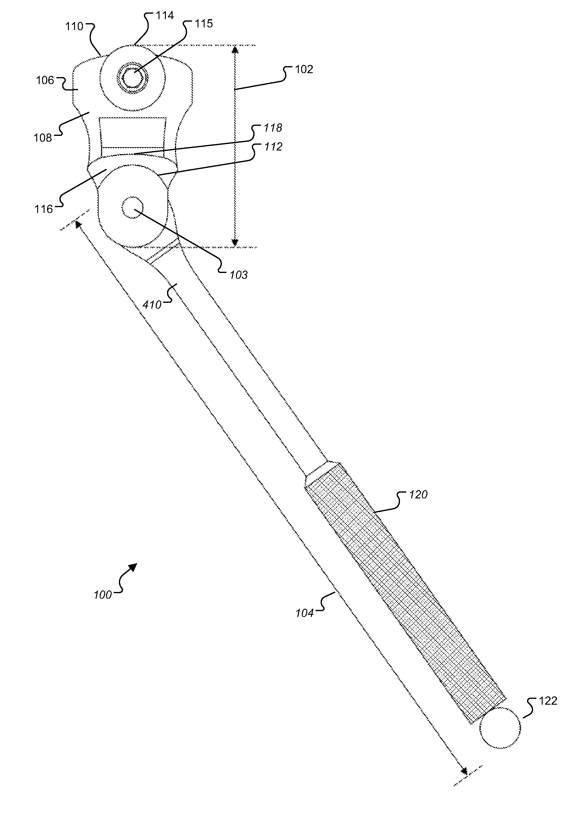
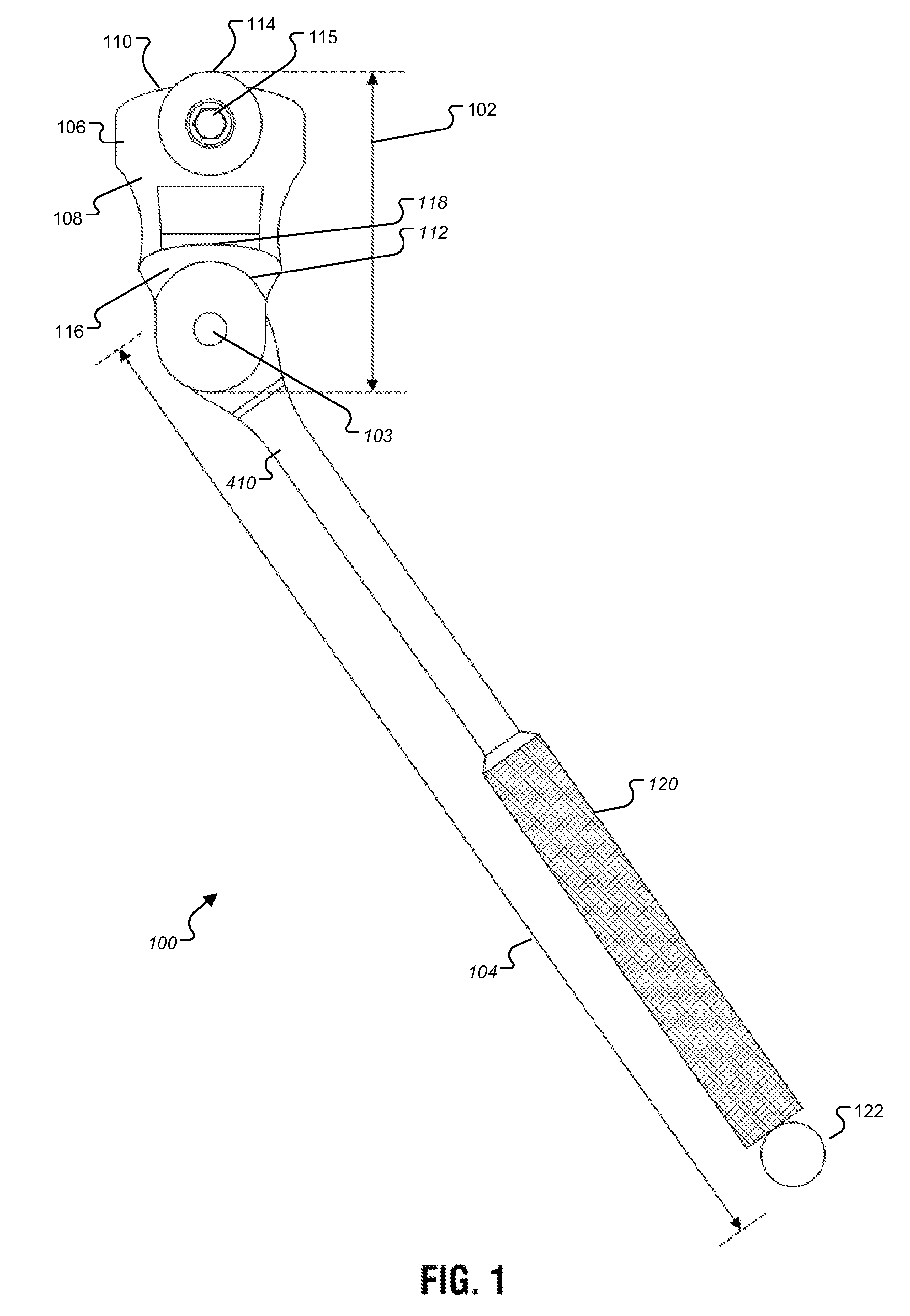
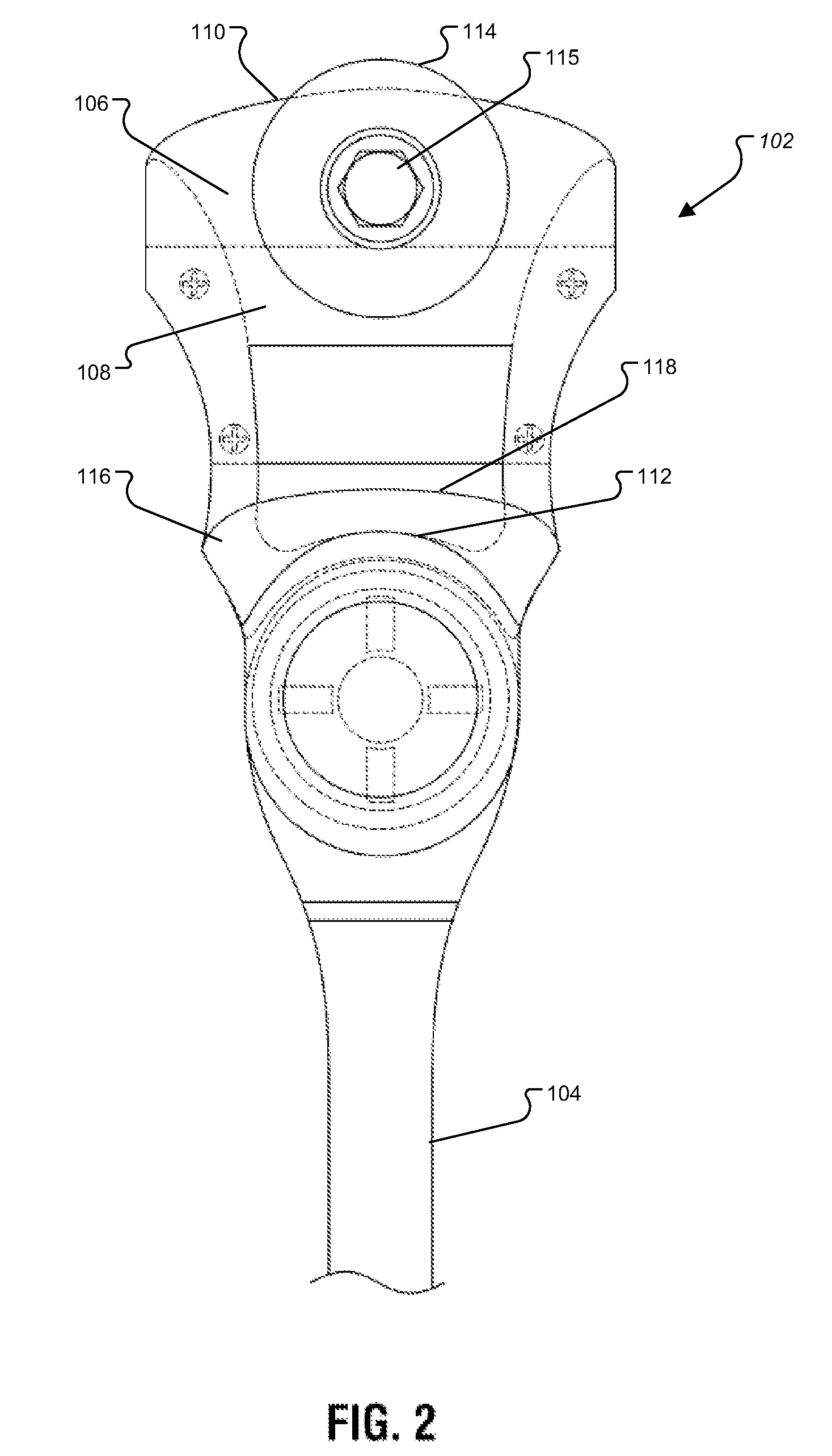
[0053]FIG. 1 is a front view of an extension tool 100 according to one embodiment of the invention. The depicted tool is employed as an extension tool to help operators reach the handbrake wheel of a train car. FIG. 2 is a close-up view of the head portion of tool 100; the details of the head portion may be better seen with respect to FIG. 2.

[0054]The tool 100 comprises a tool head 102, a connecting assembly 103, anal, a handle 104. Tool head 102 is removably attached to handle 104 by means of connecting assembly 103. The features of each part are explained in greater detail below.

[0055]With regard to FIGS. 1 and 2, tool head 102 further comprises a central body 106 with a front side 108, an upper surface 110, and a lower surface 112. A upper tapered circular rotating block 114 extends from the front side 108 of central body 106. Rotating block 114 is affixed to central body 106 by means of a rotating block fastener 115. Rotating block fastener 115 is installed so that the axis alon...


PUM


Abstract

An extension tool is provided to improve operation of handwheels, for example by allowing railroad operators to more safely reach the handbrake wheel of a train car. The tool includes a head with an upper tapered jaw designed to fit against the handwheel rim and particularly to fit the junction of the handwheel spoke and the handwheel rim circumference. The jaw may be a tapered circular rotating block. Below the jaw is a lower block designed to press against the outer circumference of the handwheel rim. The tool may also include a recess for operating a quick release lever on a train car.

Description

FIELD OF THE INVENTION[0001]The present invention relates to handheld extension tools, and more particularly, to handheld extension tools for operating a handwheel associated with a hand brake on a railroad car.BACKGROUND[0002]This invention relates to the field of tools used in the railroad industry by trainmen, carmen, and switchmen for the application and release of the most common type of hand brakes used on freight and passenger railroad cars today. Application means to set the handbrake to the stop position where the car will not move. The word release, in this context, means to put handbrake in position where the car can be moved. This type of handbrake is called a vertical wheel handbrake. It may or may not have a quick release handle, but most do. It is usually located on the end of the railroad car at a height of about seven feet from the ground to the outside circumference or rim of the handwheel.[0003]The application and release of handbrakes remains today to be one of t...

Claims


Application Information

Patent Timeline
Patent Type & Authority Patents(United States)
IPC IPC(8): B25B13/50B25G1/04
CPCB25B13/48B25B13/50
Inventor MONROE, THOMAS, P.
Owner MONROE THOMAS P
Learn More