Superimposed transmission having coupling shafts

Active Publication Date: 2014-03-04
VOITH PATENT GMBH
View PDF27 Cites 4 Cited by
  • Summary
  • Abstract
  • Description
  • Claims
  • Application Information

AI Technical Summary

Benefits of technology

The invention relates to a hydrodynamic converter with two turbine wheels connected by a spur gear transmission. The design allows for improved efficiency and flexibility in selecting the rotation direction and speed of the coupling shafts. The engageable coupling is designed as a hydrodynamic coupling, which provides elasticity and reduces the level of control required. The superimposed transmission can be operated using both converters in different rotation speed ranges, resulting in better efficiency over the entire operating range. The structure also allows for easier starting of the working machine associated with the output shaft.

Problems solved by technology

The degree of efficiency of this converter will however below 80% of the nominal rotation speed for instance be rather poor.

Method used


Image

  • Superimposed transmission having coupling shafts
  • Superimposed transmission having coupling shafts
  • Superimposed transmission having coupling shafts

Examples


Embodiment Construction

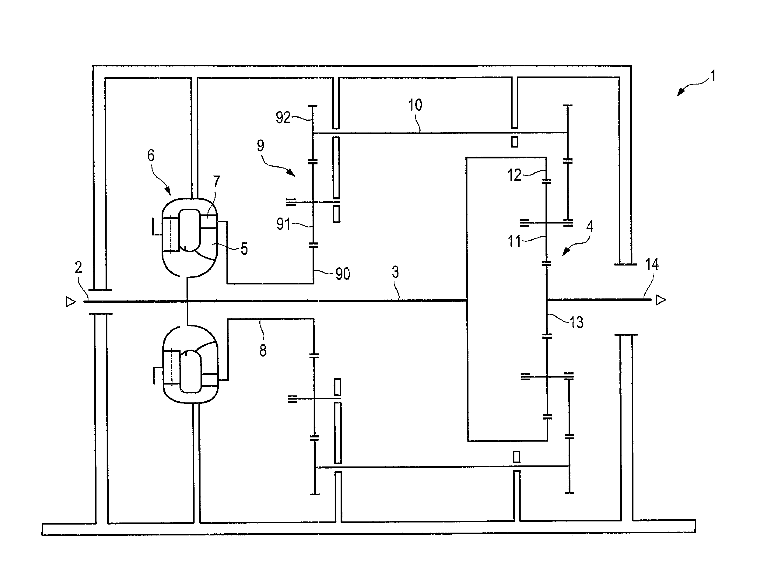
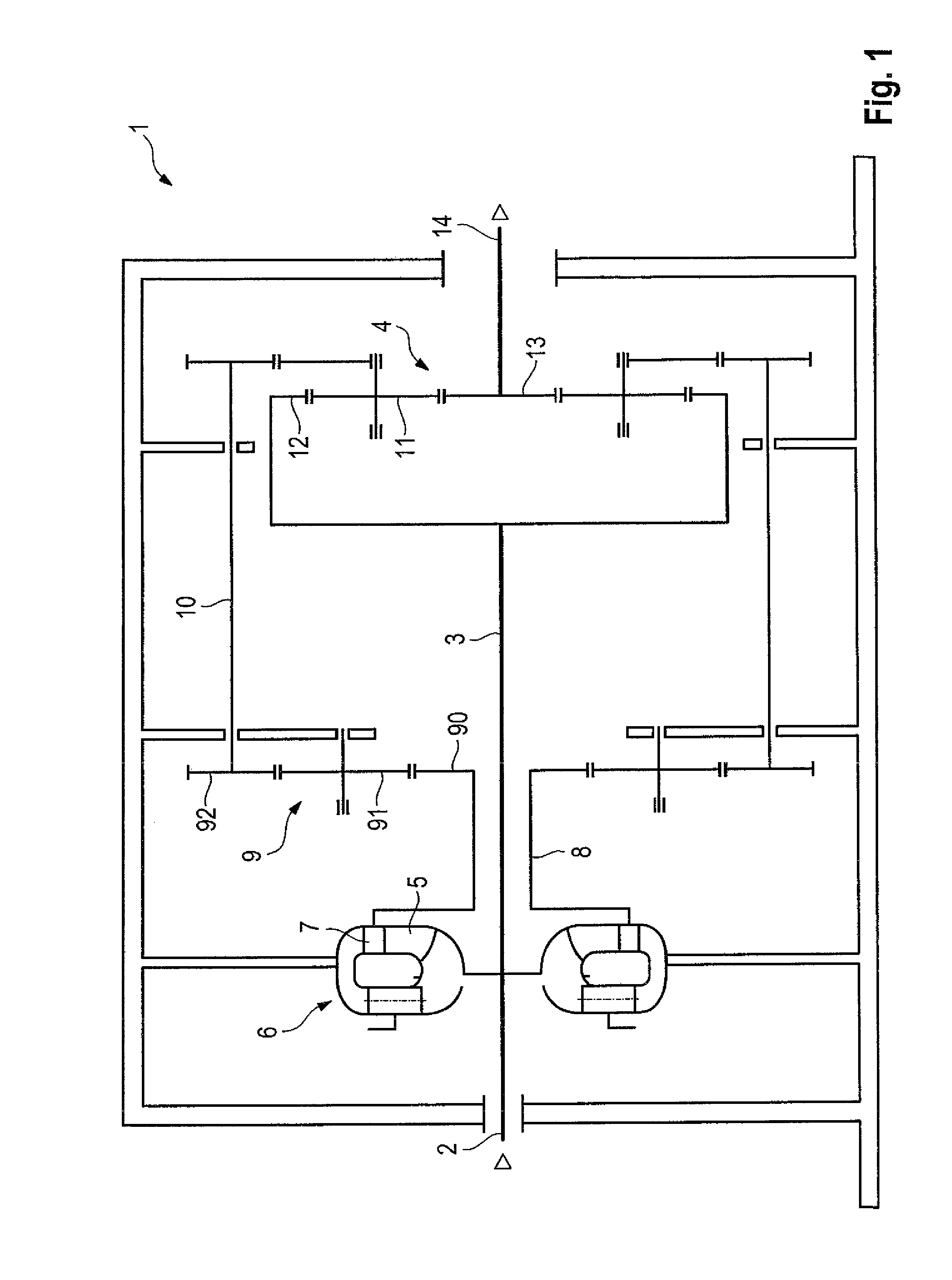
[0039]FIG. 1 clearly shows a first embodiment of the superimposed transmission 1. The structure of the superimposed transmission 1 hence includes an input shaft 2, which is connected to a intermediate shaft 3 (typically formed as a single-part with the input shaft 2) with a differential gear 4 on the one hand and the pump wheel 5 of a hydrodynamic converter 6 on the other hand. A section of the power injected into the transmission 1 over the input shaft 2 is branched off using a turbine wheel 7 of the hydrodynamic converter 6. This power is conveyed to a transmission 9 over the turbine wheel 8, which is designed as a spur gear transmission in a preferred manner. In the illustrated embodiment the spur gear transmission 9 hence shows a central toothed gear 90, which will be designed typically as a hollow wheel using the intermediate shaft 3 going therethrough. Said hollow wheel is connected to the turbine wheel 8 and consequently to the turbine 7 and drives two further toothed gears 9...


PUM


Abstract

A superimposed transmission for driving a rotational speed-variable work machine having the following design: an input shaft (2) is connected to an intermediate shaft (3); a pump wheel (5) of a hydrodynamic converter (6) rotates with the intermediate shaft (3); a turbine wheel (7) of the hydrodynamic converter (6) rotates with a superposition means; the intermediate shaft (3) and the transmission means are connected to an output shaft (14) by means of a differential gear (4); and the transmission means is designed as at least one coupling shaft (10), which connection the turbine wheel (7) of the hydrodynamic converter (6) to the differential gear (4). The at least one coupling shaft (10) runs parallel to the intermediate shaft (3). An additional hydrodynamic converter (15) can be present and / or the coupling shaft (10) can be connected in an engageable manner directly to the input shaft (2) by means of an additional transmission (18) for starting the transmission.

Description

CROSS-REFERENCE TO RELATED APPLICATION[0001]This application is related to and claims the benefit under 35 U.S.C. §119 and 35 U.S.C. §365 of International Application No. PCT / EP2009 / 005165, filed Jul. 16, 2009, the disclosure of which is expressly incorporated herein by reference.BACKGROUND[0002]1. Technical Field[0003]The invention concerns a superimposed transmission for driving a rotational speed-variable work machine having the following design:[0004]an input shaft is connected to an intermediate shaft;[0005]a pump wheel of a hydrodynamic converter rotates with the intermediate shaft;[0006]a turbine wheel of the hydrodynamic converter rotates with a superposition means; and[0007]an intermediate shaft and the transmission means are connected to an output shaft by means of a differential gear.[0008]Superimposed transmissions where a rotation speed which is applied to the output shaft via input shaft and intermediate shaft is superimposed to a second rotation speed, which is couple...

Claims


Application Information

Patent Timeline
IPC IPC(8): F16H47/08
CPCF16H47/085F16H3/095F16H47/08
Inventor SCHROTH, MARCOHAHN, KERSTENGARF, HARTMUTHILPERT, KARL
Owner VOITH PATENT GMBH
Why Eureka
Try Eureka