
Exercise machine

a technology of exercise machines and reformers, which is applied in the field of exercise machines, can solve the problems of not being able to effectively exercise certain muscle groups using the exercise reformer alone, and its ability to conduct exercises other than those listed above is very limited

Active Publication Date: 2014-02-04
LAGREE TECH INC
View PDF34 Cites 207 Cited by
  • Summary
  • Abstract
  • Description
  • Claims
  • Application Information

AI Technical Summary

Benefits of technology

The machine provides a versatile and effective means to perform a wide range of exercises, enhancing muscle tone and aesthetics while being durable, economical, and suitable for commercial use, addressing the limitations of conventional Pilates Reformer machines.

Problems solved by technology

While the Reformer has proven highly successful for its intended purpose, it is not without limitations.
To begin with, its ability to conduct exercises other than those listed above is very limited.
As a result, certain muscle groups cannot be effectively exercised using the Reformer alone.
Joseph Pilates designed other pieces of equipment to conduct exercises not possible with the Reformer, but additional equipment also means additional costs and space requirements.
Moreover, certain beneficial exercise motions are difficult or impossible to perform even with the additional pieces of equipment that Pilates designed.
A somewhat more subtle drawback of the conventional Reformer machine relates to an evolving divergence in philosophy from the traditional Pilates Method.
The original Pilates Method is founded on a comparatively small number of repetitions of precisely controlled movements, to which the conventional Reformer machine is tailored, but such a regimen does not significantly increase muscle mass beyond a relatively limited point.

Method used


Image

  • Exercise machine
  • Exercise machine
  • Exercise machine

Examples


Embodiment Construction

[0053]a. Overview

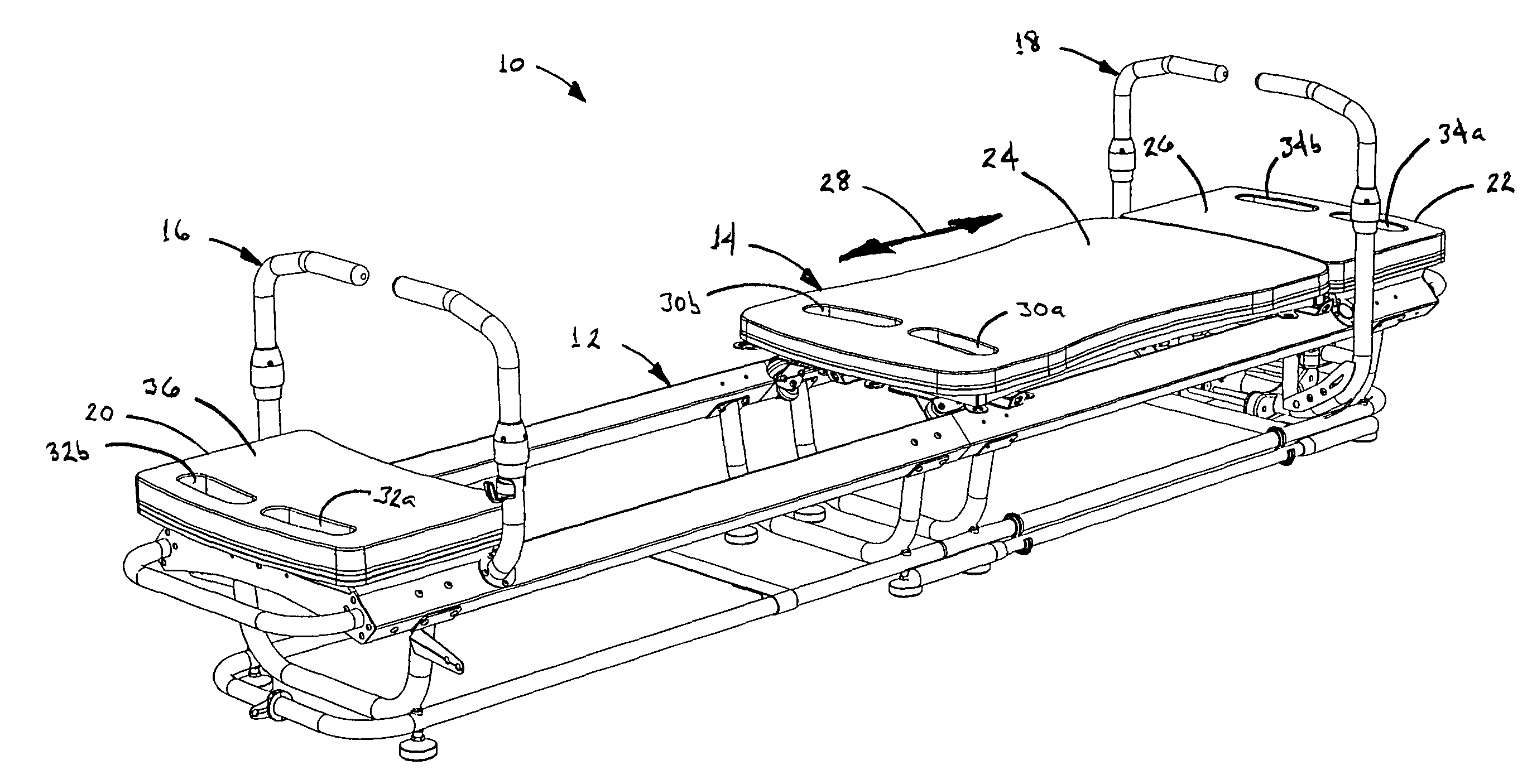
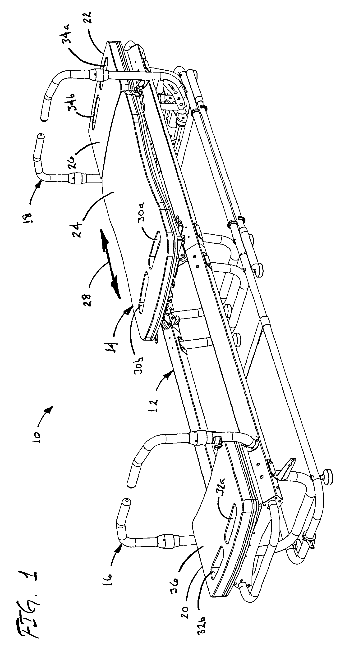
[0054]FIGS. 1-5 show an exercise machine 10 in accordance with a first preferred embodiment of the present invention. As can be seen therein, the machine includes an elongate, generally horizontal frame 12 that stands upon the floor or other substrate and provides the connections and support for the other assemblies of the machine. These include a wheeled platform assembly 14 that cooperatingly engages the frame assembly for reciprocating movement thereon, the platform being spring-biased towards a foot end of the frame as will be described in greater detail below. A first adjustable bar assembly 16 is mounted to the frame assembly 12 proximate the head end thereof, while a second adjustable bar assembly 18 is mounted proximate the foot end of the frame. In addition, stationary platforms 20, 22 are mounted at the head and foot ends of the frame assembly, distally of the respective adjustable bar assemblies 16, 18.

[0055]As used herein, “head end” and “foot end” refer...


PUM


Abstract

An exercise machine having a rolling platform and adjustable bar members. The platform is supported on frame rails, and is biased by springs towards an end of the machine. The rails have a rectangular cross-section angled 45° to horizontal, and roller assemblies on the platform include wheels angled to engage the surfaces of the rails substantially normal thereto. The adjustable bar assemblies include upwardly extending bars having upper members that are rotatable about a generally vertical axis so that handle portions at the upper ends thereof extend in different direction. At least one of the bar assemblies is also selectively pivotable about a horizontal axis to positions in which it is engaged by a locking assembly on the frame of the machine. The machine enables the user to perform a wide variety of exercises in reclined, prone, seated and standing positions, both on and off the platform.

Description

BACKGROUND[0001]a. Field of the Invention[0002]The present invention relates generally to machines for performing physical exercises, and more particularly, to an improved exercise machine that enables a person to perform a wide range of repetitive exercises in reclined, prone, seated and standing positions.[0003]b. Related Art[0004]The present invention relates somewhat to the Pilates Method physical fitness system, but provides the ability to perform certain exercises not heretofore possible with conventional Pilates-type equipment.[0005]By way of background, the Pilates Method physical fitness system was initially developed by Joseph Pilates. A German national of Greek decent, Pilates conducted physical fitness training for police officers in Britain prior to World War I. Pilates was also trained as a nurse, and while interned in Britain during World War I he investigated ways to rehabilitate bedridden victims of the 1918 influenza pandemic. The system that he developed consequen...

Claims


Application Information

Patent Timeline
Patent Type & Authority Patents(United States)
IPC IPC(8): A63B21/06
CPCA63B21/0615A63B22/0087A63B2208/0219A63B23/0355A63B21/1457A63B2208/0295A63B22/203A63B23/02A63B21/023A63B21/4029
Inventor LAGREE, SEBASTIEN, A.
Owner LAGREE TECH INC
Learn More