
Lateral mount implant device

a technology of implant device and lateral mount, which is applied in the field of lateral mount implant device and implant device, can solve the problems of abnormal angulation or slippage of the spine, affecting the structure and function of the spinal column, and experiencing extreme and debilitating pain

Inactive Publication Date: 2013-12-24
RSB SPINE
View PDF77 Cites 64 Cited by
  • Summary
  • Abstract
  • Description
  • Claims
  • Application Information

AI Technical Summary

Problems solved by technology

Various types of problems can affect the structure and function of the spinal column.
In addition congenital or acquired deformities can cause abnormal angulation or slippage of the spine.
Patients who suffer from one of more of these conditions often experience extreme and debilitating pain, and can sustain permanent neurological damage if the conditions are not treated appropriately.
However, there are disadvantages to some present stabilization devices.
Loss of alignment during the healing phase can cause a poor outcome for the patient.
The device must be secure in its attachment to the spine to prevent migration of the implant or backout of the screws from the bone, which could result in damage to the structures surrounding the spine, resulting in severe and potentially life threatening complications.
Problems have resulted from over-rigid fixation and stress shielding, resulting in nonunion of the fusion material, chronic micromotion during healing resulting in stress fracture of the fixation device at either the screw or the plate, insufficient locking of the screws to the plate resulting in screw backout, or inadequate fixation strength and resultant collapse of the graft and angulation of the spine.
For some areas of the spinal column surgical implantation may be difficult from certain directions.

Method used


Image

  • Lateral mount implant device
  • Lateral mount implant device
  • Lateral mount implant device

Examples


Embodiment Construction

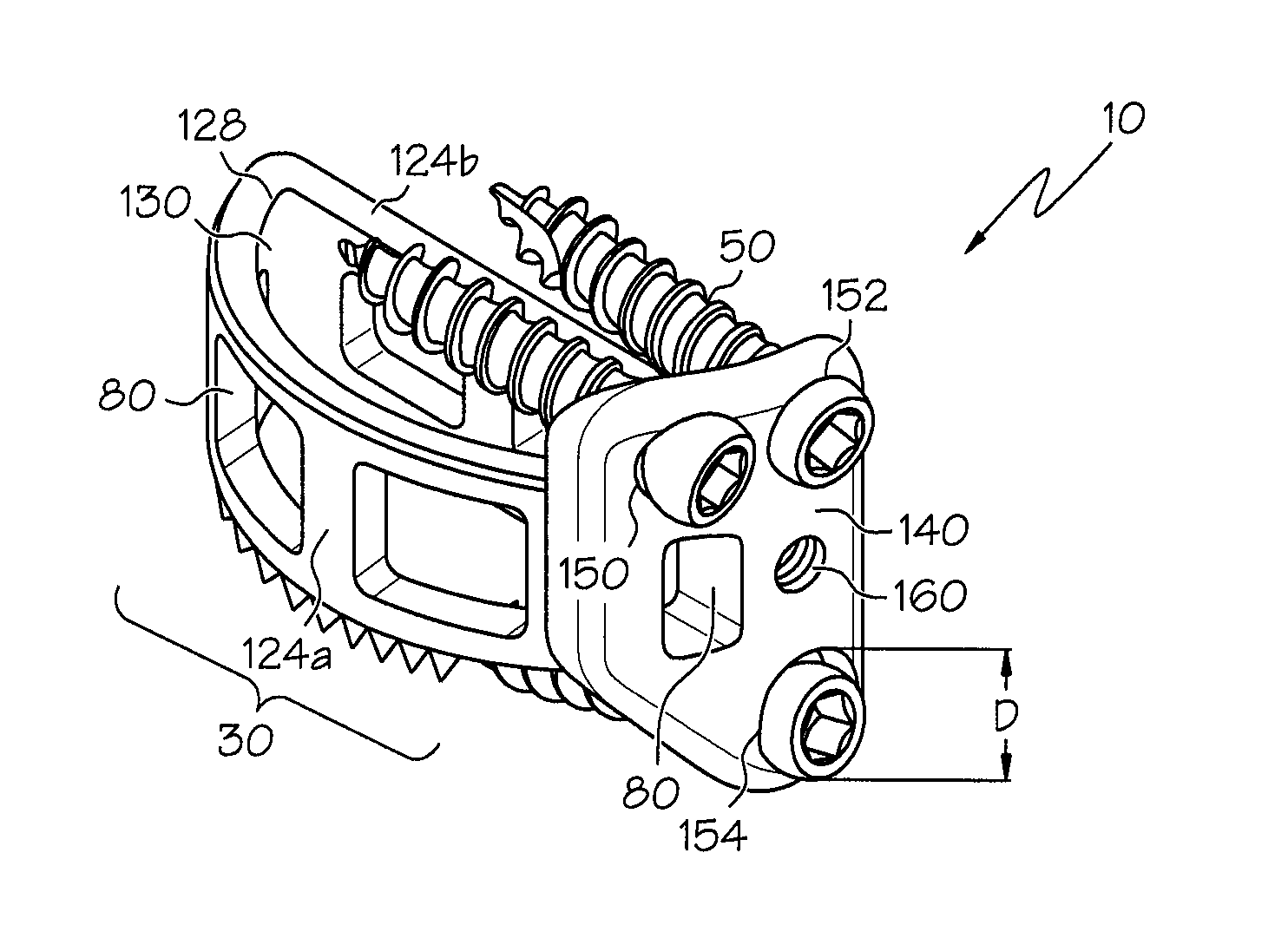
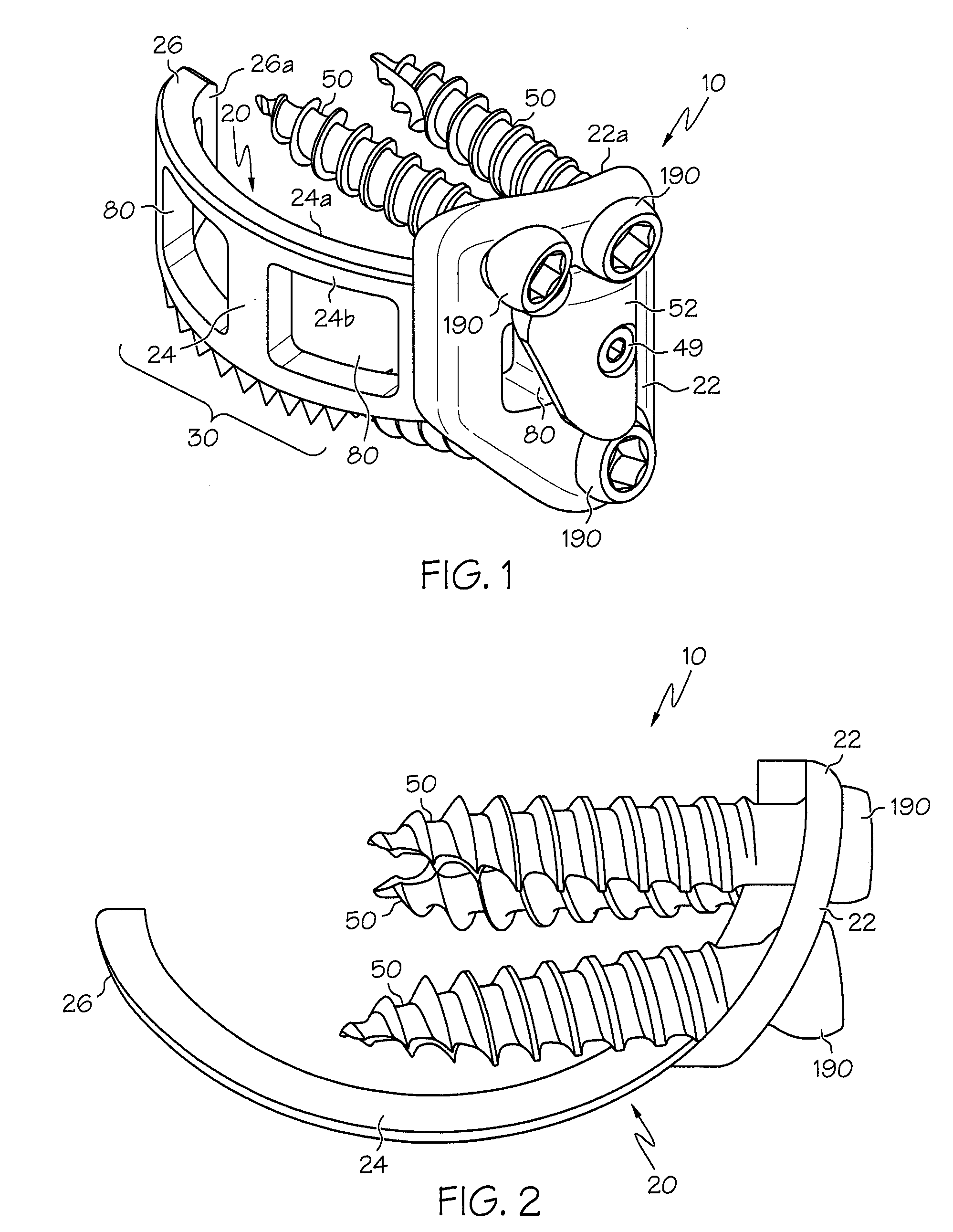
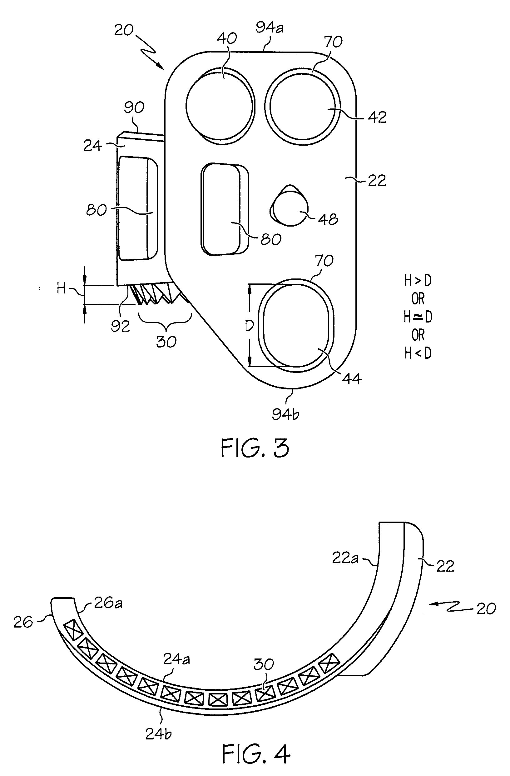
[0032]The present invention relates to an implant device that provides and controls limited movement between vertebrae during fusion. The present invention will now be described with reference to the drawings, wherein like reference numerals are used to refer to like elements throughout. It is to be appreciated that the various drawings are not necessarily drawn to scale from one figure to another nor inside a given figure, and in particular that the size of the components are arbitrarily drawn for facilitating the understanding of the drawings. In the following description, for purposes of explanation, numerous specific details are set forth in order to provide a thorough understanding of the present invention. It may be evident, however, that the present invention can be practiced without these specific details. Additionally, other embodiments of the invention are possible and the invention is capable of being practiced and carried out in ways other than as described. The terminol...


PUM


Abstract

An implant device for the spine suitable for the fixation and support of adjacent vertebrae includes a base member for implantation at a location between the two vertebrae and one or more protrusions extending from the base member. The protrusion(s) are configured for engagement with one of the vertebrae upon implantation and for progressive penetration into the vertebrae over a period of time subsequent to the implantation. The implant device includes a lateral mounting portion to accommodate fixation of the device to a lateral side of the vertebrae. The implant device is configured for insertion between the adjacent vertebrae through a posterior lateral or lateral opening that exposes a lateral side of the disc space.

Description

RELATED PATENT APPLICATION[0001]This application claims the benefit of U.S. Provisional Patent Application No. 60 / 782,795 filed Mar. 16, 2006, and claims the benefit of and is a continuation in part application of U.S. patent application Ser. No. 11 / 620,255 filed Jan. 5, 2007, now U.S. Pat. No. 8,100,976, and U.S. patent application Ser. No. 11 / 248,651 filed Oct. 12, 2005, now U.S. Pat. No. 7,985,255, both of which claim benefit of and are continuations-in-part applications of U.S. patent application Ser. No. 10 / 419,652 filed Apr. 21, 2003, now U.S. Pat. No. 6,984,234, the contents of all of which are incorporated herein by reference in their entirety.BACKGROUND OF THE INVENTION[0002]1. Field of the Invention[0003]The present invention relates generally to devices for the fixation and support of vertebrae. In particular, the present invention relates to an implant device having a lateral mounting portion that provides and controls limited movement between the vertebrae during fusion...

Claims


Application Information

Patent Timeline
Patent Type & Authority Patents(United States)
IPC IPC(8): A61F2/44
CPCA61F2/4455A61F2/446A61F2/30965A61F2002/2835A61F2002/30113A61F2002/30131A61F2002/30187A61F2002/30517A61F2002/30578A61F2002/30777A61F2002/30787A61F2002/30843A61F2002/30845A61F2002/4475A61F2220/0025A61F2230/0006A61F2230/0013A61F2230/0034A61F2310/00017A61F2310/00023A61F2310/00029A61F2002/30593
Inventor BRAY, ROBERT S.MORAN, JAMES M.WHITEAKER, MARK T.
Owner RSB SPINE
Learn More