
Rowing machine simulator

a simulator and rowing machine technology, applied in the field of rowing simulators or rowing machines, can solve the problems of increasing the likelihood of injury to the knee, back and shoulders of the oarsman, and the simulator does not properly simulate the forces to which the oarsman is exposed, so as to reduce the operating arc and stabilize the simulator

Inactive Publication Date: 2013-12-17
ROWPERFECT
View PDF117 Cites 13 Cited by
  • Summary
  • Abstract
  • Description
  • Claims
  • Application Information

AI Technical Summary

Benefits of technology

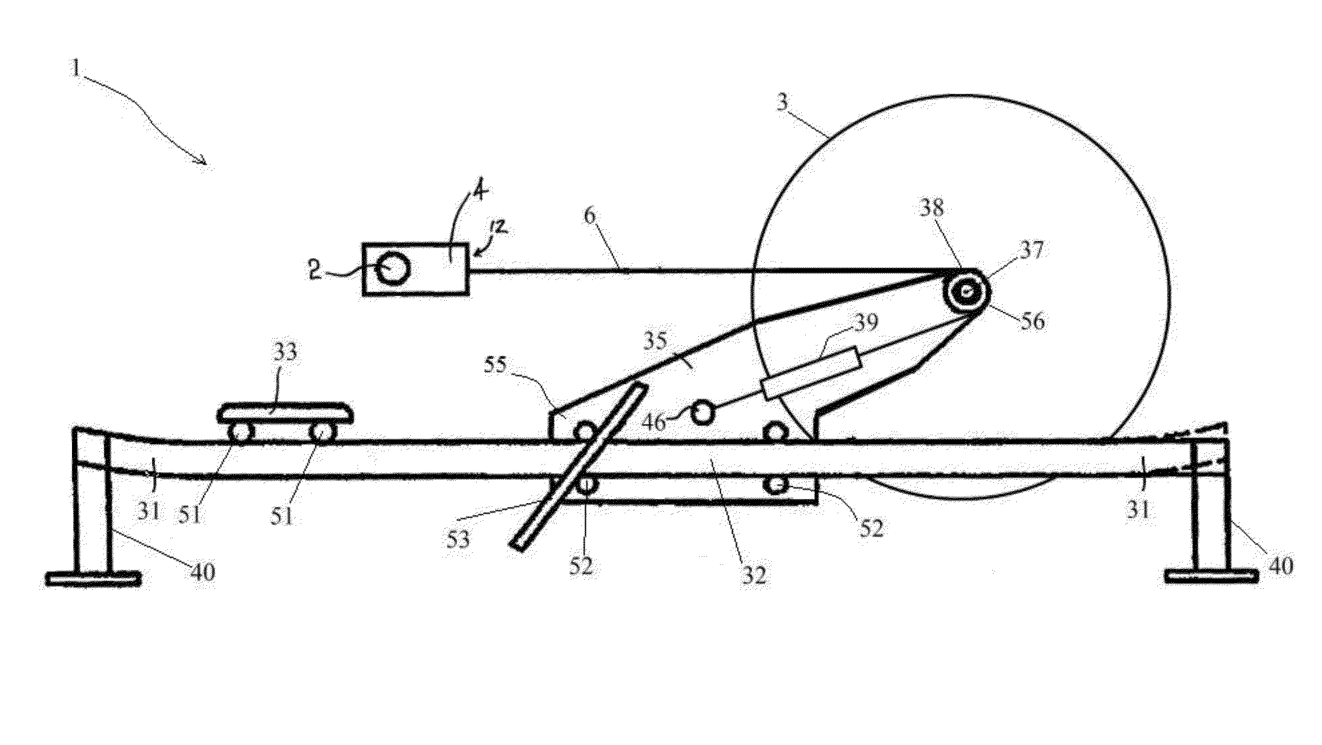
The patent describes a better simulator for getting people to row using a dynamically balanced machine. The simulator is made with a flywheel at a low height, which makes it more stable and reduces the space needed for it. This also makes it easier for people to use.

Problems solved by technology

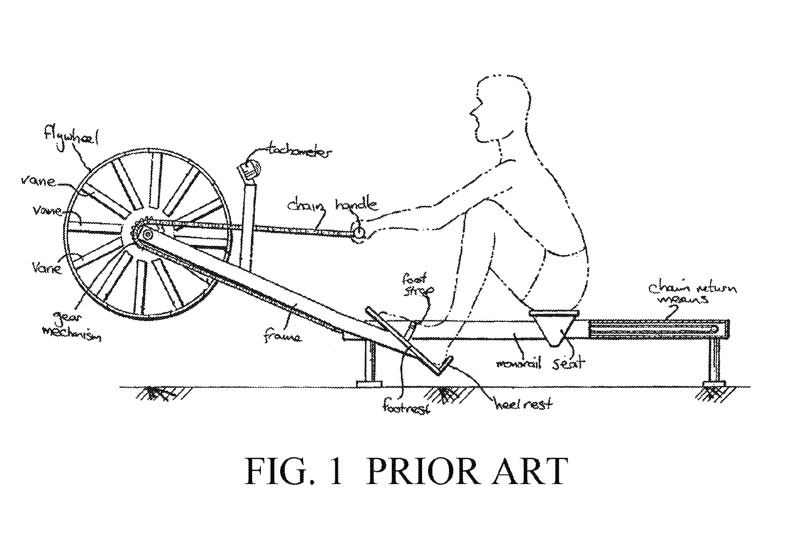
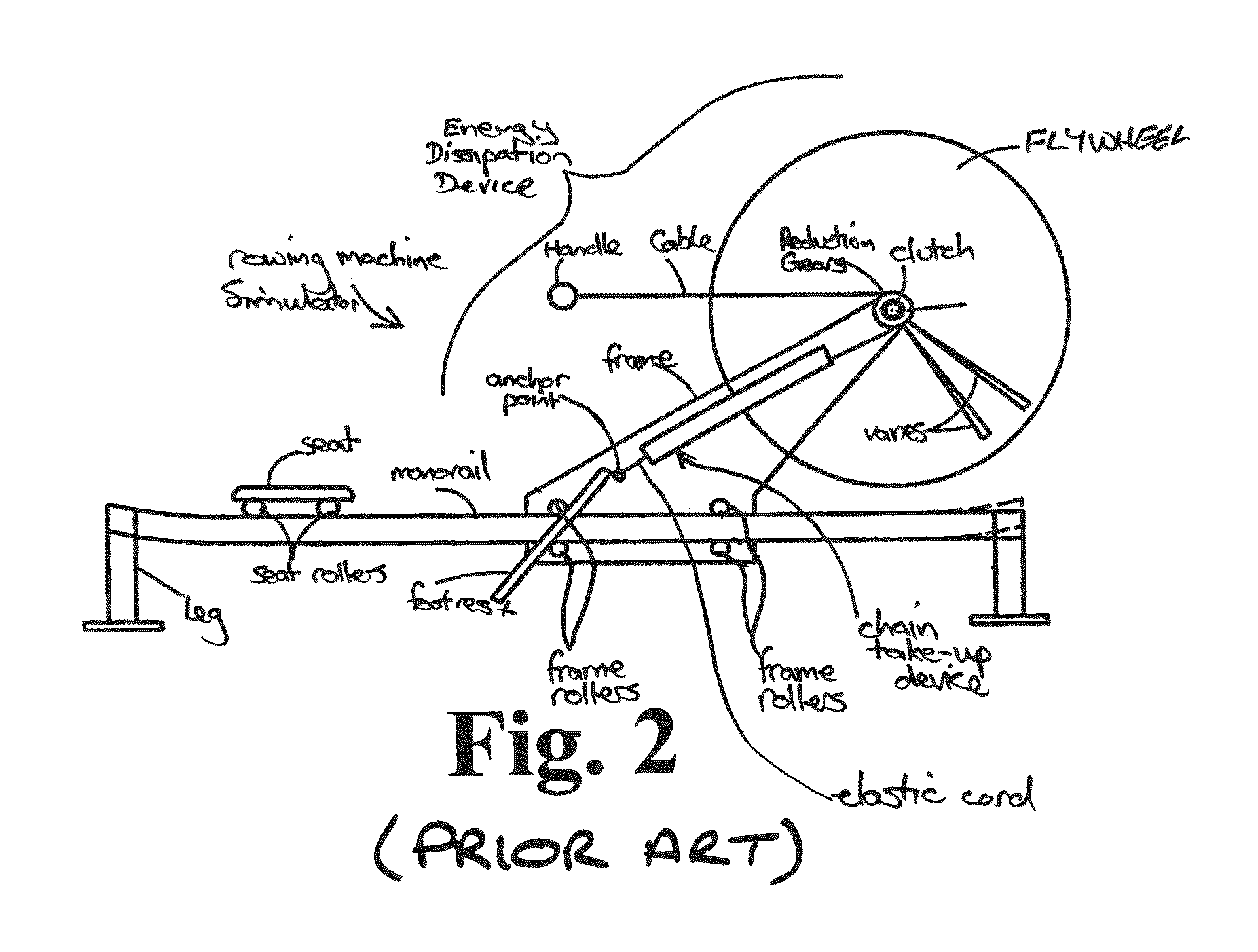
Unfortunately, static rowing simulators such as the example shown in FIG. 1 do not properly simulate the forces an oarsman is exposed to during normal rowing action.
As such, the known static rowing simulators are acknowledged by health professionals as being potentially detrimental to the oarsman by increasing the likelihood of injury to the oarsman's knee, back and shoulders.
Another disadvantage of the prior art is a propensity to become unstable during use when an oarsman is pulling on the handle.

Method used


Image

  • Rowing machine simulator
  • Rowing machine simulator
  • Rowing machine simulator

Examples


Embodiment Construction

[0030]In the following Detailed Description, reference is made to the accompanying drawings, which form a part hereof, and in which is shown by way of illustration specific embodiments in which the invention may be practiced. In this regard, directional terminology, such as “top,”“bottom,”“front,”“back,”“leading,”“trailing,” etc., is used with reference to the orientation of the Figure(s) being described. Because components of embodiments can be positioned in a number of different orientations, the directional terminology is used for purposes of illustration and is in no way limiting. It is to be understood that other embodiments may be utilized and structural or logical changes may be made without departing from the scope of the present invention. The following detailed description, therefore, is not to be taken in a limiting sense, and the scope of the present invention is defined by the appended claims.

[0031]It is to be understood that the features of the various exemplary embodi...


PUM


Abstract

One aspect is a rowing machine with a longitudinally extending beam and a seat mounted to said beam and slidable therealong. A frame is mounted to said beam and slidably movable therealong independently of said seat. A pair of foot rests are mounted to a user end of said frame. A flywheel is rotatably mounted by a flywheel shaft to said frame, said flywheel shaft mounted to said frame a height less than a radius of said flywheel above said beam. The flywheel is drivable by a cable through a transmission mechanism mounted to said frame such that one end of said cable remote from said flywheel is connected to a handgrip and the other end of said cable connected to a cable take up mechanism.

Description

CROSS-REFERENCE TO RELATED APPLICATIONS[0001]This application is a Continuation-in-Part of patent application Ser. No. 12 / 018,702, filed Jan. 23, 2008 entitled, “Rowing Machine Simulator,” which claims priority to Australian Provisional Patent Application No. 2007900315 filed Jan. 23, 2007, all of which are incorporated herein by reference.BACKGROUND[0002]One aspect relates to rowing simulators or rowing machines. One embodiment has been developed primarily for use with dynamically balanced rowing simulators and will be described hereinafter with reference to this application. However, it will be appreciated that the invention is not limited to this particular field of use and is applicable to many different types of rowing simulators as would be understood by a person skilled in the art.[0003]Static rowing simulators or machines have been long known for use in both general strength and fitness training, or for use specifically for oarsmen to practice their rowing. In these known st...

Claims


Application Information

Patent Timeline
Patent Type & Authority Patents(United States)
IPC IPC(8): A63B69/06
CPCA63B22/0076A63B22/0087A63B2022/0079A63B2071/0063A63B21/225A63B2220/70A63B21/0552A63B21/0087A63B2071/0072A63B21/023A63B21/05A63B22/203A63B22/0012
Inventor CAMPBELL, MARK
Owner ROWPERFECT
Learn More