
Bone conduction device having limited range of travel

limited technology, applied in the direction of transducer casings/cabinets/supports, electrical transducers, electrical apparatus, etc., can solve the problems of conductive hearing loss, impede the normal mechanical pathway that provides sound to hair cells in the cochlea, and not all individuals suffering from conductive hearing loss are able to derive suitable benefits from hearing aids. , to achieve the effect of preventing damage to a bone conduction devi

Active Publication Date: 2013-11-26
COCHLEAR LIMITED
View PDF47 Cites 0 Cited by
  • Summary
  • Abstract
  • Description
  • Claims
  • Application Information

AI Technical Summary

Benefits of technology

The bone conduction device effectively transfers vibrations to the skull, reducing the risk of damage and providing a suitable solution for individuals with conductive hearing loss who cannot benefit from traditional hearing aids or cochlear implants, while minimizing discomfort and feedback.

Problems solved by technology

Conductive hearing loss occurs when the normal mechanical pathways that provide sound to hair cells in the cochlea are impeded, for example, by damage to the ossicular chain or ear canal.
Unfortunately, not all individuals suffering from conductive hearing loss are able to derive suitable benefit from hearing aids.
Furthermore, hearing aids are typically unsuitable for individuals who suffer from single-sided deafness (total hearing loss only in one ear).
Additionally, in order to prevent undesirable acoustic feedback, hearing aids generally require that the ear canal be occluded, resulting in unnecessary pressure, discomfort, or other undesirable side effects such as eczema.

Method used


Image

  • Bone conduction device having limited range of travel
  • Bone conduction device having limited range of travel
  • Bone conduction device having limited range of travel

Examples


Embodiment Construction

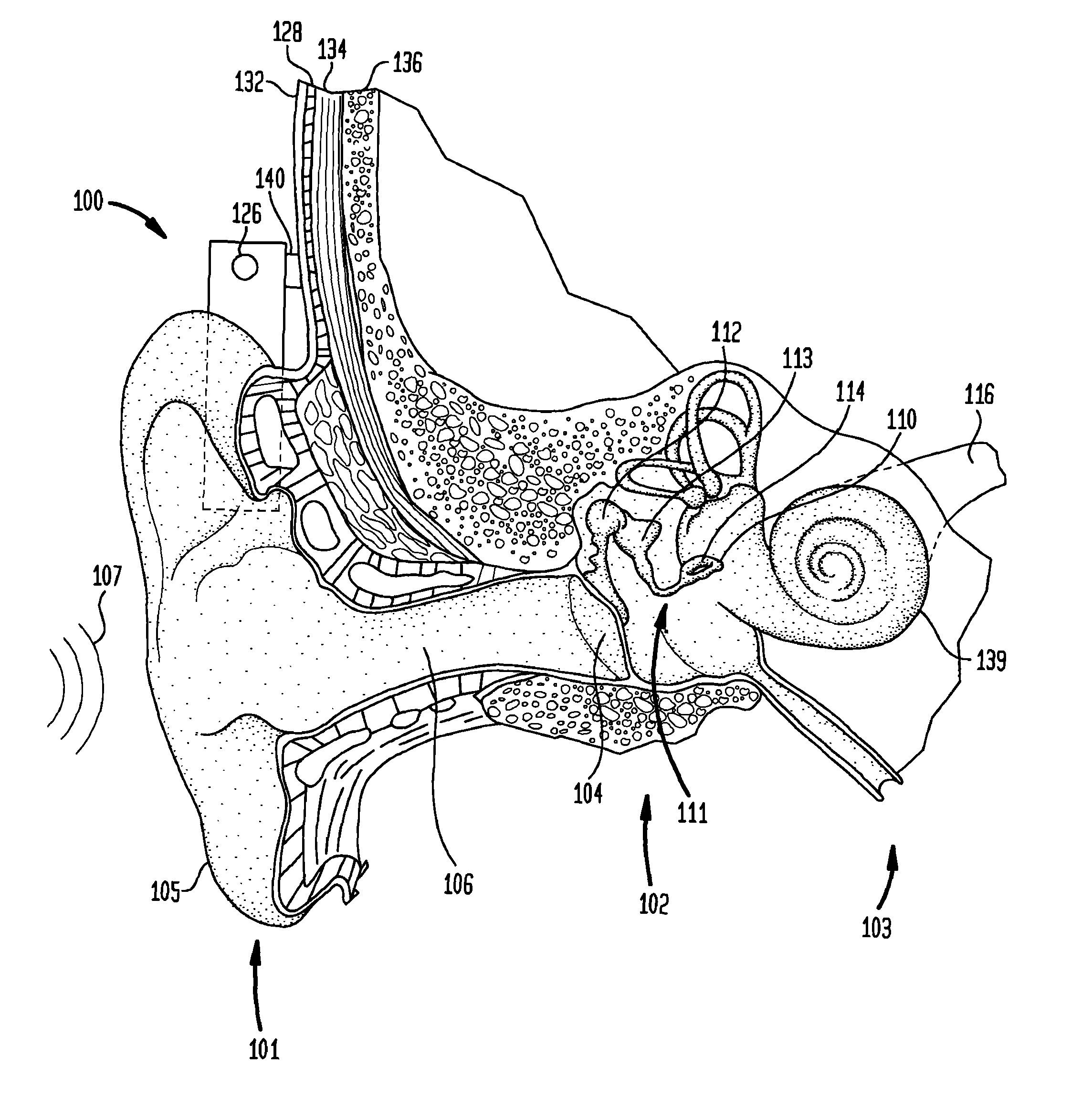
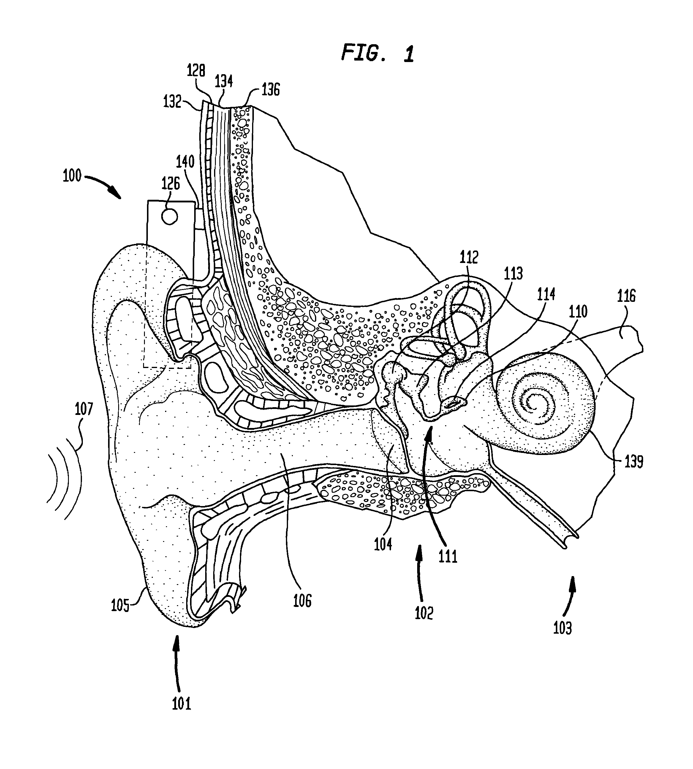
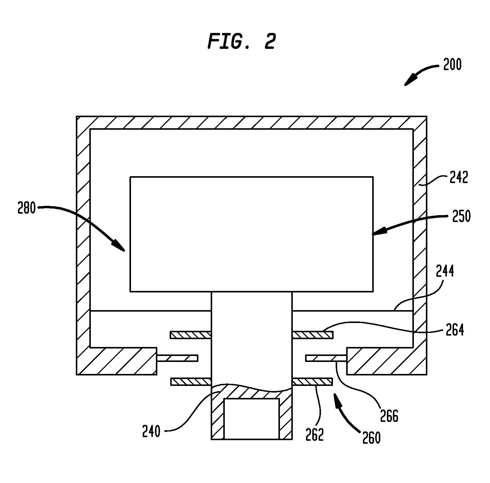
[0021]Aspects of the present invention are generally directed to a bone conduction device in which the range of travel of device components is limited to reduce the likelihood of damage to the device. In an exemplary embodiment, the bone conduction device comprises a housing, a vibrating actuator, a coupling apparatus and a travel limit apparatus. The coupling apparatus is removably attached to an anchor system implanted in the recipient. The actuator is suspended in the housing and attached to the coupling apparatus to facilitate the transfer of vibrations to the recipient's skull. When the device is attached / detached to / from the anchor system, the travel limit apparatus limits movement of the housing relative to the coupling apparatus and the vibrating actuator preventing the actuator from contacting the housing.

[0022]FIG. 7 is a schematic diagram of a bone conduction device including a travel limit apparatus, in accordance with an embodiment of the invention;

[0023]FIG. 1 is a per...


PUM


Abstract

A bone conduction device configured to couple to an abutment of an anchor system anchored to a recipient's skull. The bone conduction device includes a housing and a vibrating actuator movably suspended in the housing and configured to vibrate in response to sound signals received by the bone conduction device The bone conduction device further includes a coupling apparatus configured to attach the bone conduction device to the abutment so as to deliver to the recipient's skull vibrations generated by the vibrating actuator, and a travel limit apparatus configured to limit a range of travel of the housing relative to the coupling apparatus.

Description

BACKGROUND[0001]1. Field of the Invention[0002]The present invention relates generally to hearing prostheses, and more particularly, to a bone conduction device having a limited range of travel.[0003]2. Related Art[0004]Hearing loss, which may be due to many different causes, is generally of two types: conductive and sensorineural. Sensorineural hearing loss is due to the absence or destruction of the hair cells in the cochlea that transduce sound signals into nerve impulses. Various hearing prostheses are commercially available to provide individuals suffering from sensorineural hearing loss with the ability to perceive sound. For example, cochlear implants use an electrode array implanted in the cochlea of a recipient to bypass the mechanisms of the ear. More specifically, an electrical stimulus is provided via the electrode array directly to the auditory nerve, thereby causing a hearing percept.[0005]Conductive hearing loss occurs when the normal mechanical pathways that provide ...

Claims


Application Information

Patent Timeline
Patent Type & Authority Patents(United States)
IPC IPC(8): H04R25/00
CPCH04R11/02H04R2460/13
Inventor AHSANI, SAMI
Owner COCHLEAR LIMITED
Learn More