
Landing gear

a technology of supporting legs and gears, applied in the field of extension support legs, can solve the problems of reducing affecting the service life and the first stage of extension of the telescopic column can become extremely slow, and the gear change is rather complicated to realize, so as to reduce the rotation of the drive shaft and minimise the torque

Active Publication Date: 2013-11-12
SIMOL
View PDF27 Cites 6 Cited by
  • Summary
  • Abstract
  • Description
  • Claims
  • Application Information

AI Technical Summary

Benefits of technology

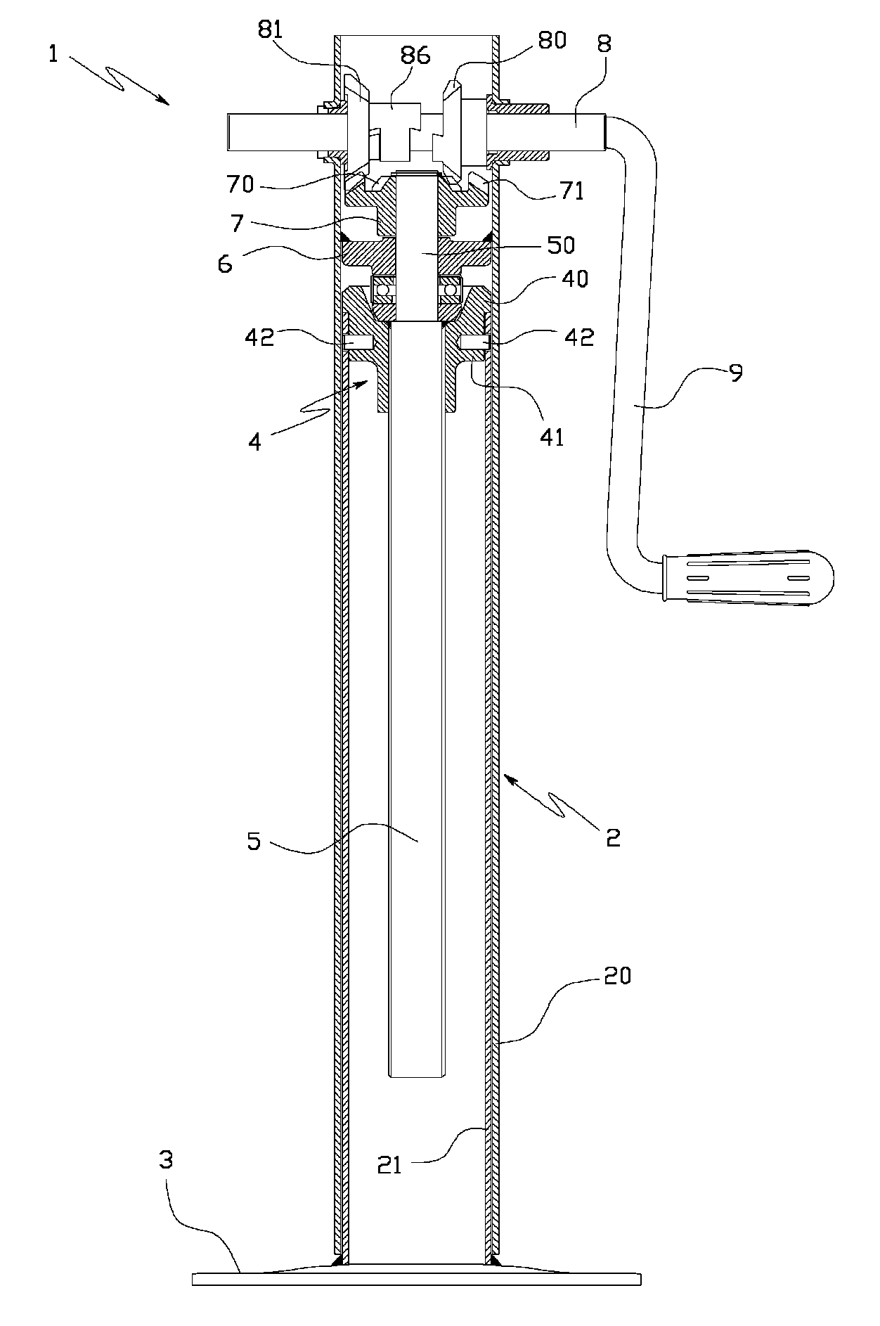
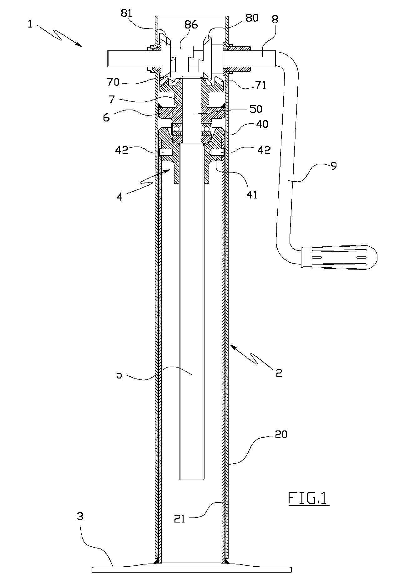
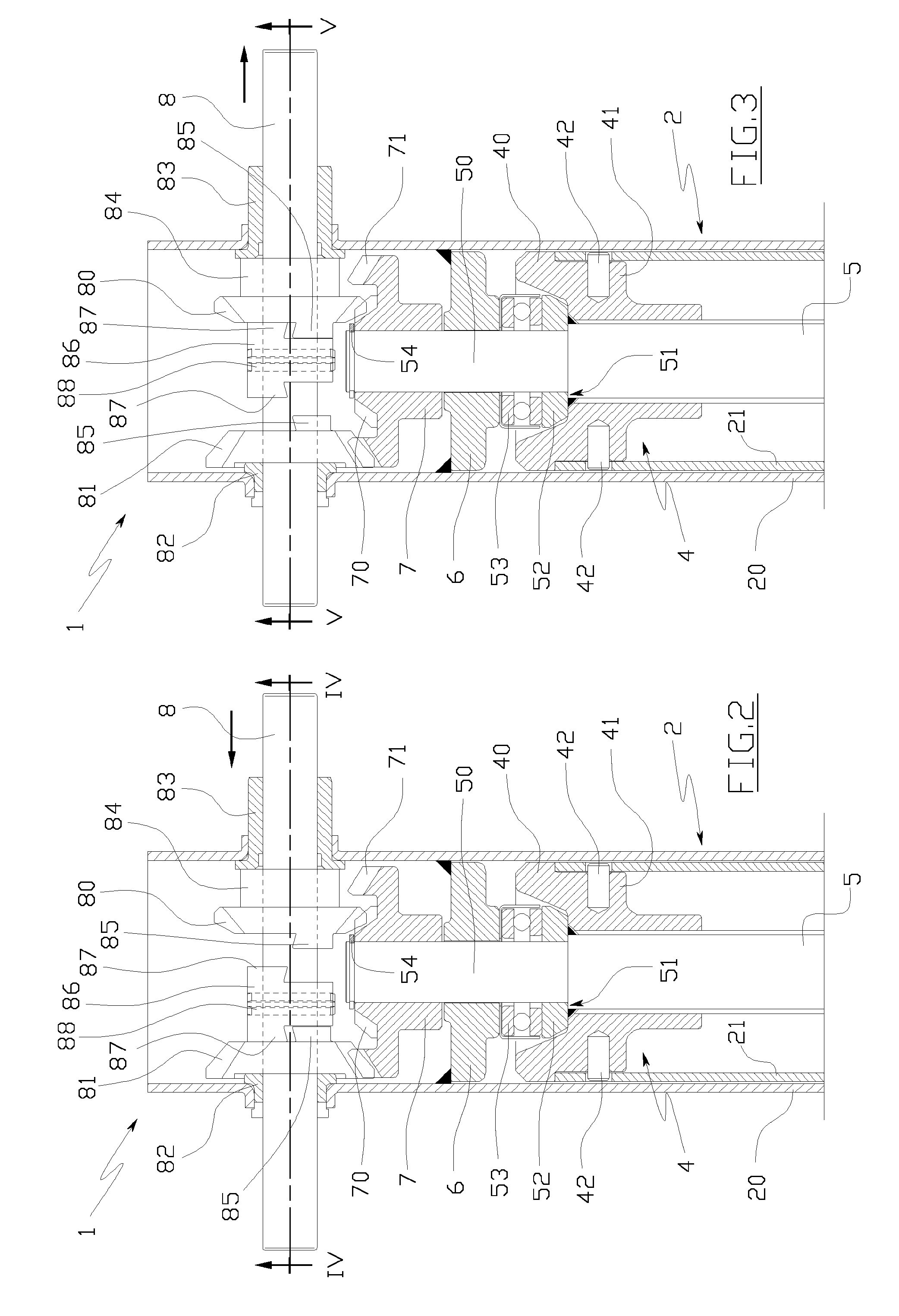
[0035]Thanks to this solution, no intermediate shaft is necessary between the drive shaft and the manoeuvring screw, thus considerably simplifying the realisation of the gear change, which is therefore more economical and compact with respect to all the solutions at present known in the prior art.
[0037]The lower transmission ratio can be used in the first stage of extension of the support leg, such as to reduce the revolutions of the drive shaft required, and therefore the time needed in order to bring the support organ to the ground.
[0038]The higher transmission ratio can be used in the second stage of extension of the support leg, such as to minimise the torque to be applied to the drive shaft in order to obtain the raising of the load.
[0041]This makes the support leg very compact, simple and economical.
[0045]This solution has the advantage of providing an enmeshing system which is very simple and reliable.
[0047]This solution reduces the number of components, and simplifies the mounting of the gear change.

Problems solved by technology

This fact can represent a drawback, as it means in particular that the first stage of extension of the telescopic column, i.e. the stage which is necessary for resting the contact organ on the ground, can become an extremely slow operation.
Though providing good results, these solutions require the use and mounting of numerous mechanical components and cog wheels, making the gear change rather complicated to realise, as well as expensive.
Further, the gear changes realised in the above known solutions are very unwieldy, and increase the overall dimensions of the support leg, which obviously makes a larger space necessary for mounting thereof on-board vehicles.

Method used


Image

  • Landing gear
  • Landing gear
  • Landing gear

Examples


second embodiment

[0121]In FIGS. 6 and 7 a support leg 1 is illustrated which shows the invention.

[0122]This second embodiment is structurally and functionally similar to the preceding one, and differs from it only in some constructional aspects, the most important of which are delineated in the following.

[0123]Firstly, the gearings 80, 81, 70, 71 of the gear change are contained internally of a separate casing 22 which is welded to the top of the external tube 20.

first embodiment

[0124]The bottom wall of the casing 22 replaces the plate 6 in the first embodiment, and the drive shaft 8 is inserted internally of the holes which are afforded in the lateral walls of the casing 22.

[0125]No plastic bushing is provided between the drive shaft 8 and the respective holes.

[0126]The gear wheel 81 is therefore directly rested against a lateral wall of the casing 22, while the gear wheel 80 is rested against the opposite lateral wall with only the interposing of a spacer 84.

[0127]The activating handle 9 is fashioned in a single body with the drive shaft 8.

[0128]The external cogged crown wheel 71 and the internal cogged crown wheel 70 are realised in two separate bodies 7′ and 7″, which are coaxially inserted on the tract of cylindrical spur 50 which projects internally of the casing 22.

[0129]Naturally the external cogged crown wheel 71 and the internal cogged crown wheel 70 could in this case too be realised in a single body as in the preceding embodiment.

[0130]The exter...


PUM


Abstract

An extensible support leg includes at least two reciprocally-slidable portions, a maneuvering screw axially constrained to a first portion, a threaded volute axially constrained to a second portion and screwed on the maneuvering screw, and a rotating drive shaft which is connected to the maneuvering screw by a mechanical gear change, and is rotatable to set the maneuvering screw in rotation. The mechanical gear change includes: two first cogged crown wheels, coaxial and rotatably solid with the maneuvering screw; two second cogged crown wheels mounted coaxially and rotatably idle on the drive shaft, which enmesh directly with a respective first cogged crown wheel, realizing two gears having different transmission ratios; and a cursor, which is solidly rotatably associated to a portion of the drive shaft between the second cogged crown wheels, and is mobile, in a direction of the drive shaft axis, between first and second enmeshed positions.

Description

TECHNICAL FIELD[0001]The invention relates to support legs which are normally fitted to trailers, construction machines, agricultural machines, industrial vehicles, transport carriages or any type of vehicle to enable stable support thereof on the ground when the machine is stationary.[0002]In particular, the present invention relates to extensible support legs which can take on a shortened configuration, in which the lower end thereof is raised from the ground, and an extended configuration, in which the lower end thereof rests on the ground.BACKGROUND ART[0003]As is known, extensible support legs schematically comprise a telescopic column which is fixed to the vehicle, and a contact organ which is fixed to the lower end of the telescopic column.[0004]The contact organ is generally a platform or a small wheel.[0005]The telescopic column comprises at least two coaxial tubes, of which one is an external tube and another is an internal tube which is slidably inserted in the external t...

Claims


Application Information

Patent Timeline
Patent Type & Authority Patents(United States)
IPC IPC(8): B60S9/02
CPCB60S9/08
Inventor RIGHETTI, VALTER
Owner SIMOL
Learn More