
Riser tensioner system

a riser tensioner and tensioner technology, applied in the direction of sealing/packing, drilling pipes, wellbore/well accessories, etc., can solve the problems of frame with significantly reduced strength, prone to early failure, and difficult fabrication, so as to reduce the required vertical spacing, eliminate costly offshore assembly and possible system damage and contamination, and minimal vertical spacing of the deck

Active Publication Date: 2013-11-12
THE TECH ALLIANCE INC DBA OILPATCH TECH
View PDF37 Cites 9 Cited by
  • Summary
  • Abstract
  • Description
  • Claims
  • Application Information

AI Technical Summary

Benefits of technology

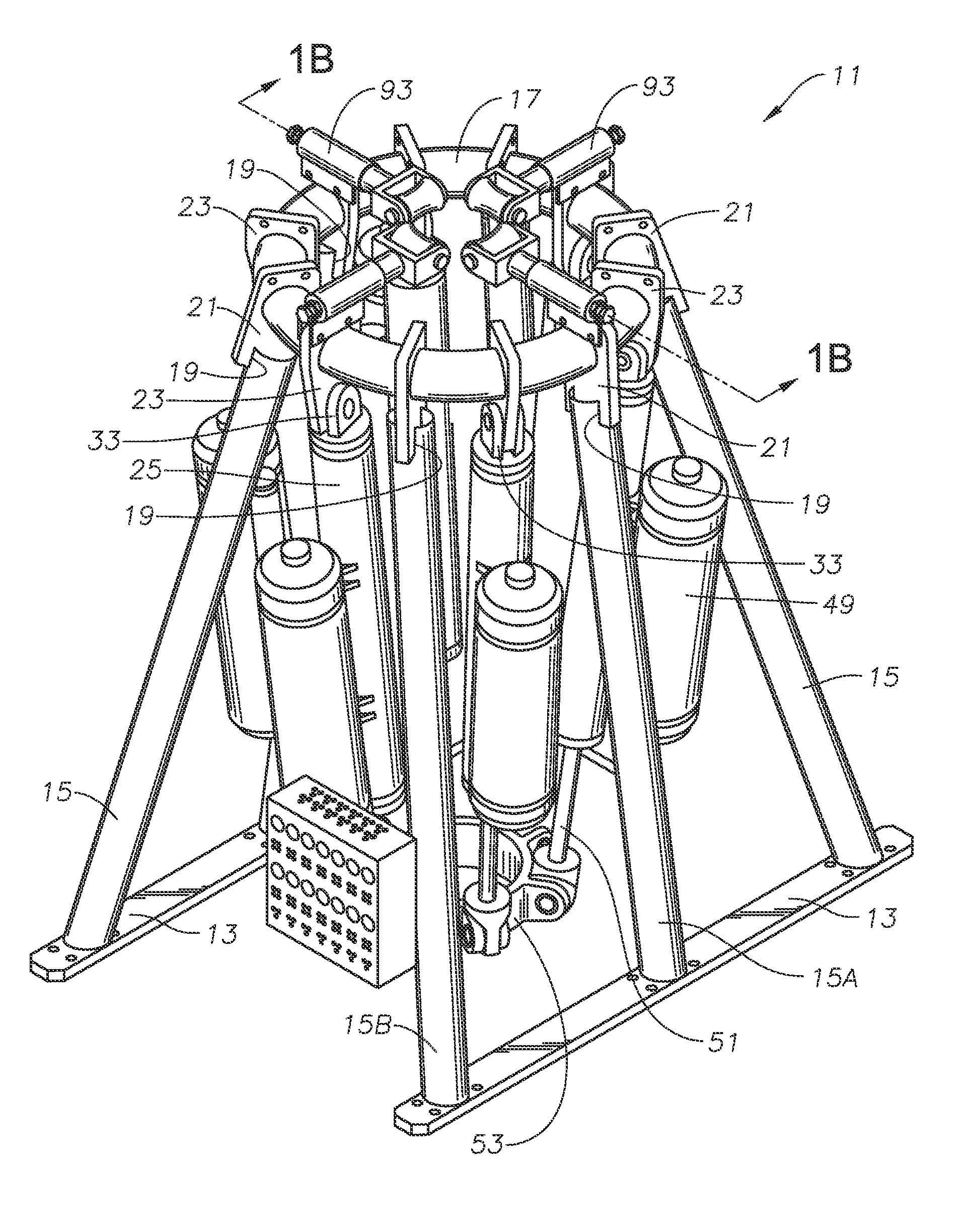
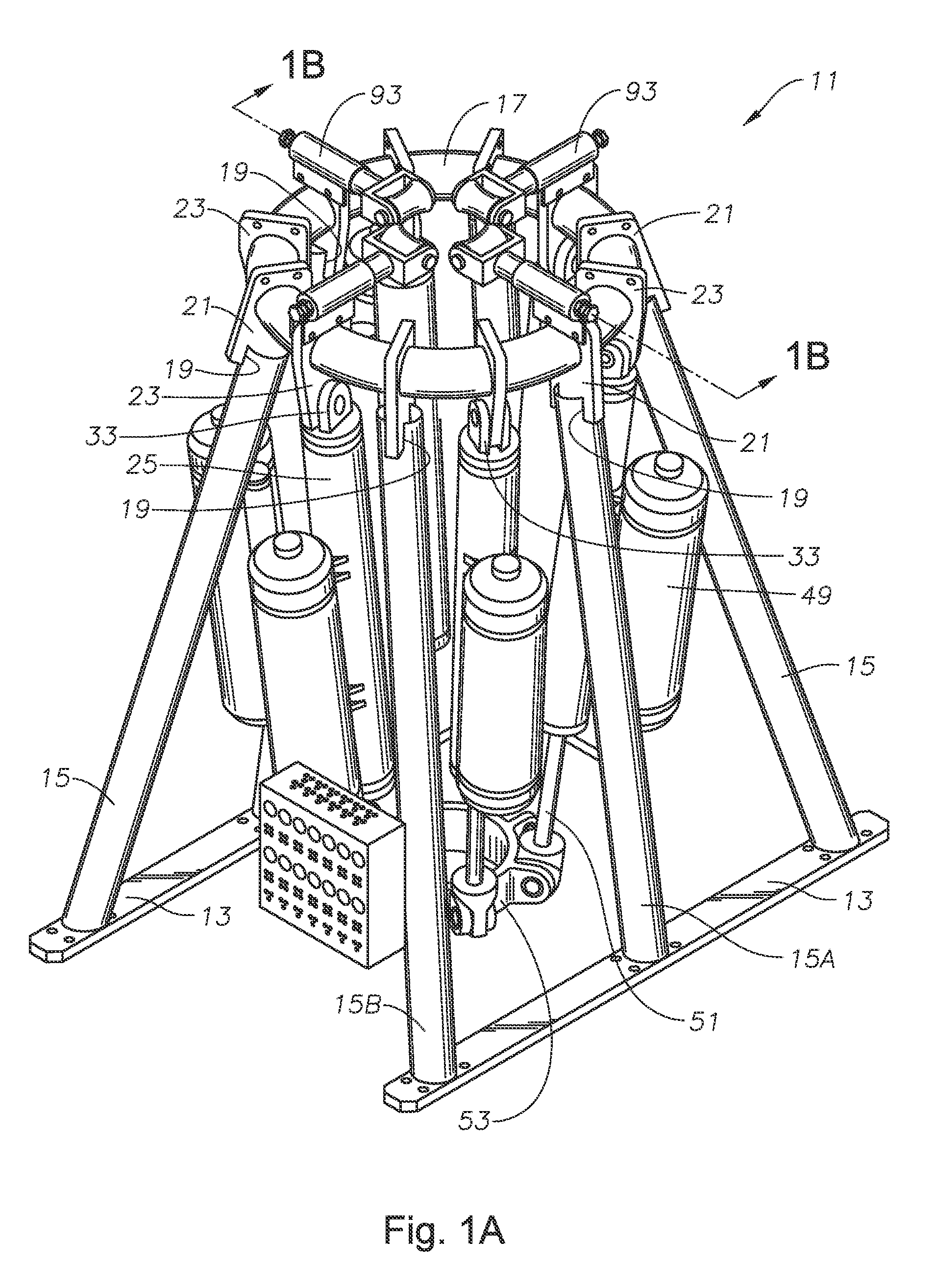
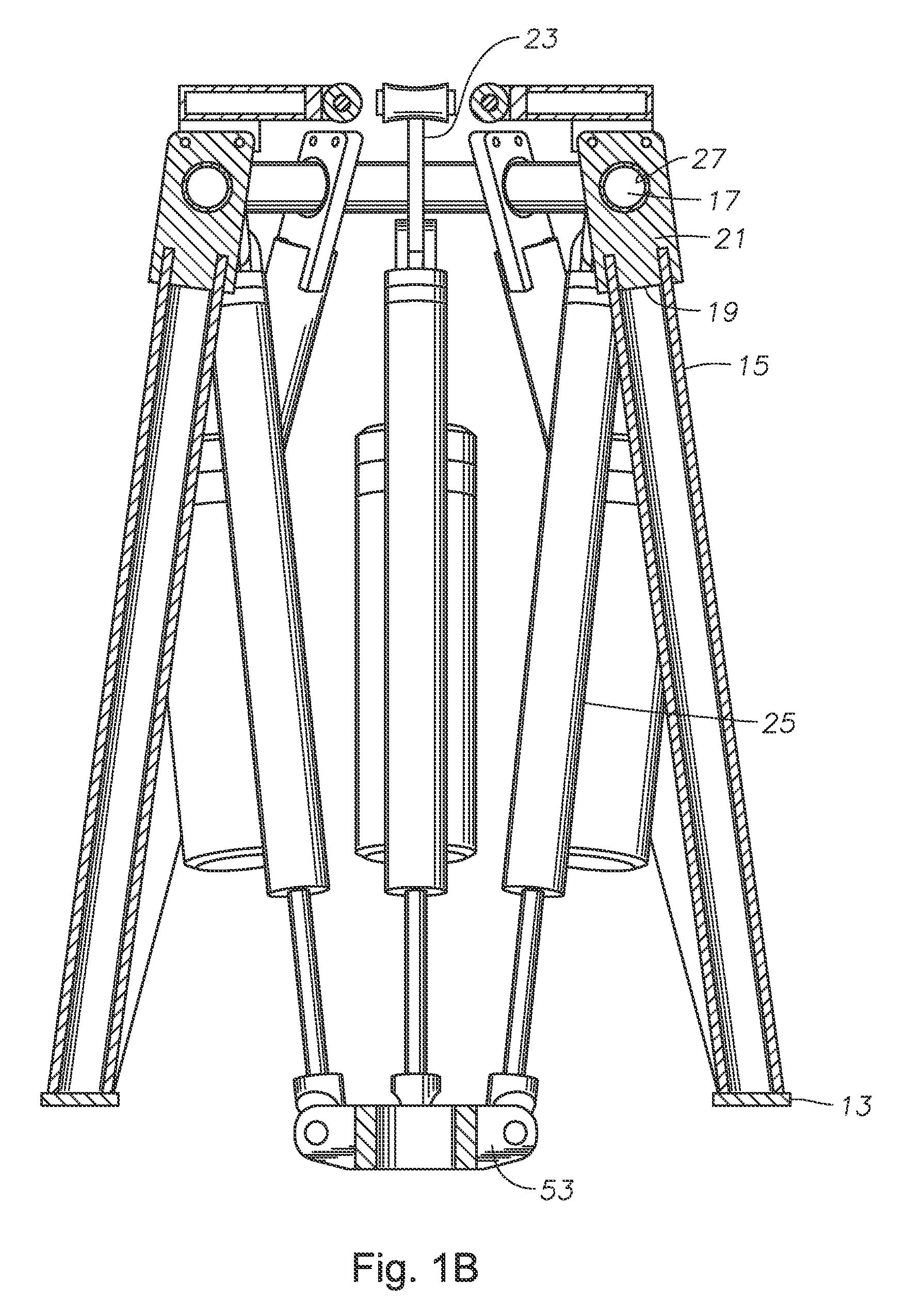
[0013]The disclosed embodiments provide numerous advantages. For example, the resulting tensioner system's height is less than one that utilizes prior art designs, such as those using dual shackles to couple the cylinders to the frame. This decreases the required vertical spacing between decks on a platform, allowing for minimal vertical spacing of the decks. The riser tensioner system is a complete put-together assembly, function and pressure tested prior to shipment to an offshore facility. This eliminates costly offshore assembly and possible system damage and contamination due to the offshore environment. The disclosed embodiments also allow for installation and repair of the riser tensioner system without the need of a risky keel hauling process. Thus, on platforms with multiple installed risers, the riser tensioner system disclosed herein may be installed, repaired, or removed without shutting in production through the platform during the process as may otherwise be required during a standard keel hauling process.
[0014]Unlike prior art designs, the primary load path of the disclosed tensioner passes directly from the frame, through the leg attachment plate and into the frame leg, without placing primary structural load bearing on the joining welds mounting each element to the next. This provides a stronger more efficient frame structure. It is more efficient in transferring loads, less sensitive to deflection induced stress hot-spots, easier to fabricate and inspect, and less expensive. In addition, mounting the pivoting member, i.e. the swivel bearing, to the stationary tensioner frame will cause the tensioning loads to remain perpendicular to the pivoting member and the tensioner frame, thereby eliminating eccentric loading of the pivoting mount.

Problems solved by technology

This may create problems as the riser tensioner frame must be sufficiently strong to react to the lateral loading by the riser.
Generally, each component is welded together and, due to the angled and coped joints, this makes for difficult fabrication.
Thus, the strength of the tensioner is placed on welds that may be located in positions and angles that are difficult to form.
Improper welding may lead to a frame with a significantly reduced strength that is prone to early failure.
The lugs are mounted to the tensioner frame ring and, due to the shape and fabrication of the tensioner frame ring, may be difficult to place and weld properly.
In addition, the shackles provide an undesired increase in length of the tensioner element that necessitates a taller tensioner system.
Still further, the shackles are exposed to environmental conditions that cause rapid wear of the shackles at the interfacing surfaces of the shackles.
In some embodiments, the tensioner elements are coupled with swivel bearings however, the arrangement of the tensioner frame ring, lugs, and frame legs may cause eccentric loading of the swivel bearing that leads to early failure.
These issues make fabrication and in place repair of riser tensioner systems difficult.

Method used


Image

  • Riser tensioner system
  • Riser tensioner system
  • Riser tensioner system

Examples


Embodiment Construction

[0031]The present invention will now be described more fully hereinafter with reference to the accompanying drawings which illustrate embodiments of the invention. This invention may, however, be embodied in many different forms and should not be construed as limited to the illustrated embodiments set forth herein. Rather, these embodiments are provided so that this disclosure will be thorough and complete, and will fully convey the scope of the invention to those skilled in the art. Like numbers refer to like elements throughout, and the prime notation, if used, indicates similar elements in alternative embodiments.

[0032]In the following discussion, numerous specific details are set forth to provide a thorough understanding of the present invention. However, it will be obvious to those skilled in the art that the present invention may be practiced without such specific details. Additionally, for the most part, details concerning well drilling, running operations, and the like have ...


PUM


Abstract

A riser tensioner system maintains a tensile force in a riser having an axis and extending from a subsea wellhead assembly through an opening in a floating platform deck. The tensioner includes a plurality of tensioner legs having lower ends mounted to the deck, and upper ends having slots formed therein to receive leg attachment plates having an opening therein through which a tubular support ring passes. A plurality of cylinders extend between the tubular support ring and a tensioner ring and couple to the support ring with cylinder attachment plates through which the tubular support ring passes. An upper end of each cylinder pivots about the mounting point, and a lower end of each cylinder adjustably mounts to the tensioner ring.

Description

[0001]This application claims priority to and the benefit of U.S. Provisional Application No. 61 / 471,530, filed on Apr. 4, 2011, entitled “Riser Tensioner System” to Paul C. Berner, Jr., et al, which application is hereby incorporated in its entirety herein by reference.FIELD OF THE INVENTION[0002]The present invention relates in general to marine riser tensioners and, in particular, to a riser tensioner frame for a riser tensioner system.BRIEF DESCRIPTION OF RELATED ART[0003]Offshore production platforms must support production risers from oil or gas wells that extend to the platform from subsea wells. This is accomplished through the use of riser tensioners or riser tensioning mechanisms that hold the riser in tension between the production platform and the wellhead. The riser tensioning mechanism maintains the riser in tension so that the entire weight of the riser is not transferred to the wellhead and to prevent the riser from collapsing under its own weight. The tensioning mec...

Claims


Application Information

Patent Timeline
Patent Type & Authority Patents(United States)
IPC IPC(8): E21B19/00
CPCE21B19/002
Inventor BERNER, JR., PAUL C.MOORE, SAMMY RUSSELLCOX, WILLIAM ROBERT
Owner THE TECH ALLIANCE INC DBA OILPATCH TECH
Learn More