
Quick-release device

a quick-release device and a technology of a fork are applied in the direction of release mechanisms, cycle equipment, rod connections, etc., and can solve the problems of inconvenient rotation and detachment of the conventional quick-release device from the fork, unbalance of the load of the conventional quick-release device to the fork (b>4/b>),

Active Publication Date: 2013-11-05
CHANG CHIN CHAO
View PDF6 Cites 20 Cited by
  • Summary
  • Abstract
  • Description
  • Claims
  • Application Information

AI Technical Summary

Benefits of technology

The present invention provides an improved quick-release device that includes a lever for easy detachment. The device includes a shank with a flange and a ring, connected by a sleeve with a through hole. A pivotal lever is connected to the ring and a washer is secured to the second section of the through hole in the sleeve. The lever includes a handle for easy engagement and is selectively operable to drive the shank for safe and quick release. The technical effects of this improved quick-release device are improved efficiency and ease of use, allowing for quick and safe detachment of components.

Problems solved by technology

However, the fork (4) usually has two parallel tubes such that the load for the conventional quick-release device to the fork (4) is unbalance.
It is inconvenient to rotate and detach the conventional quick-release device from the fork (4).

Method used


Image

  • Quick-release device
  • Quick-release device
  • Quick-release device

Examples


Embodiment Construction

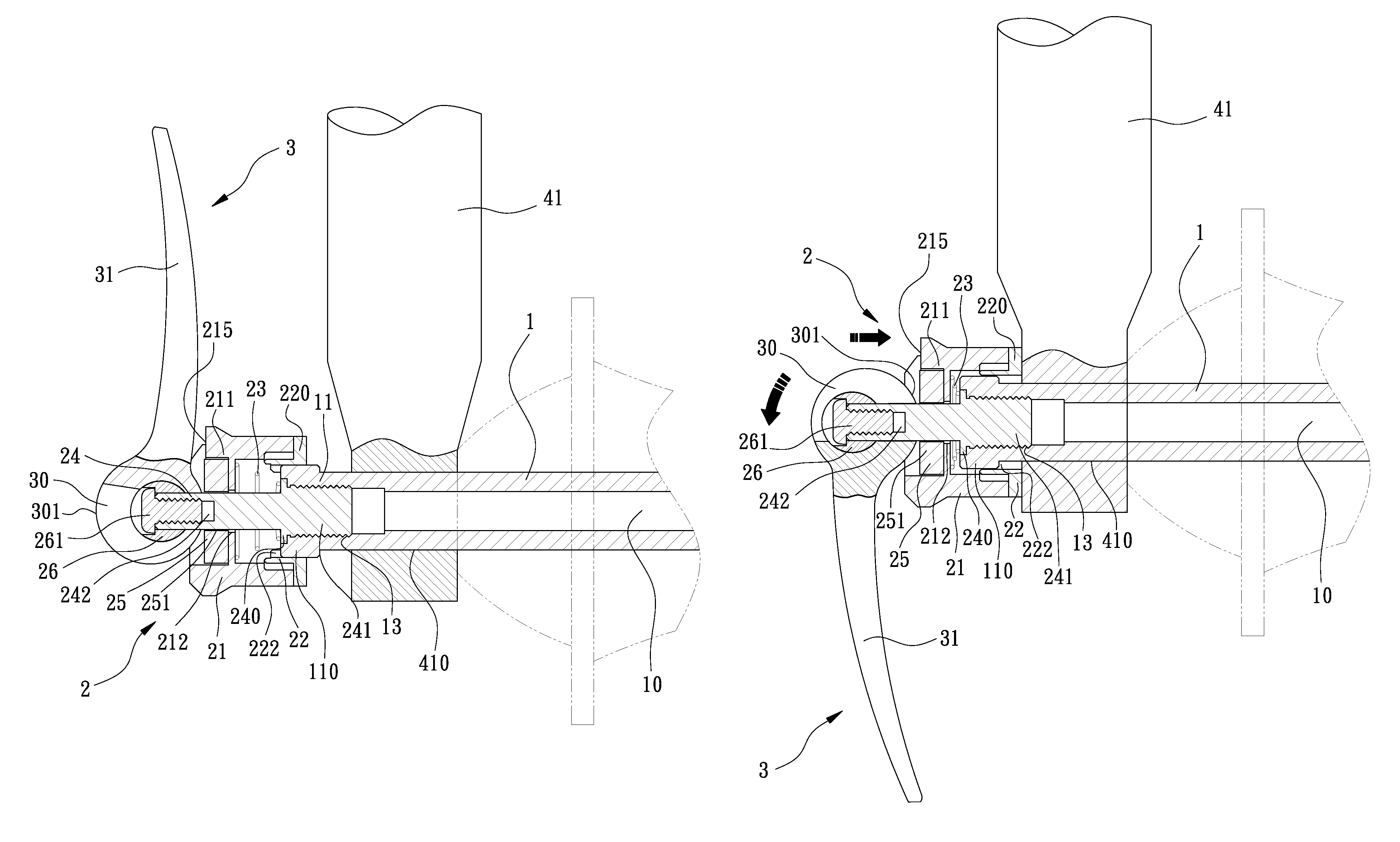
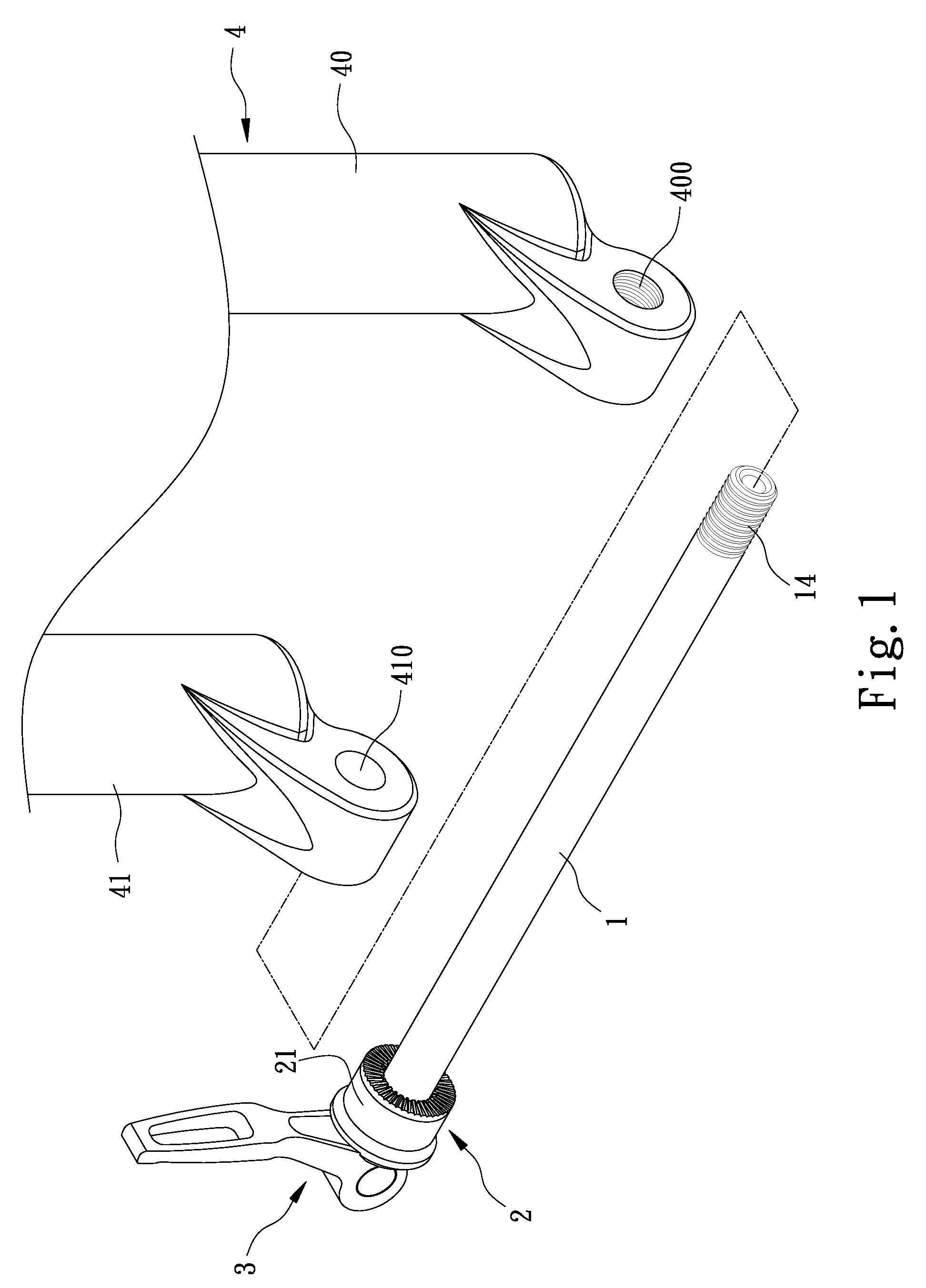
[0023]Referring to the drawings and initially to FIGS. 1-4, a quick-release device in accordance with the present invention is adapted to be mounted on a fork (4) that has a first tube (40) and a second tube (41) parallel to each other, wherein the first tube (40) has a threaded hole (400) transversely defined in a free end thereof and the second tube (41) has a through hole (410) transversely defined in a free end thereof. The threaded hole (400) and the through hole (410) align with each other.

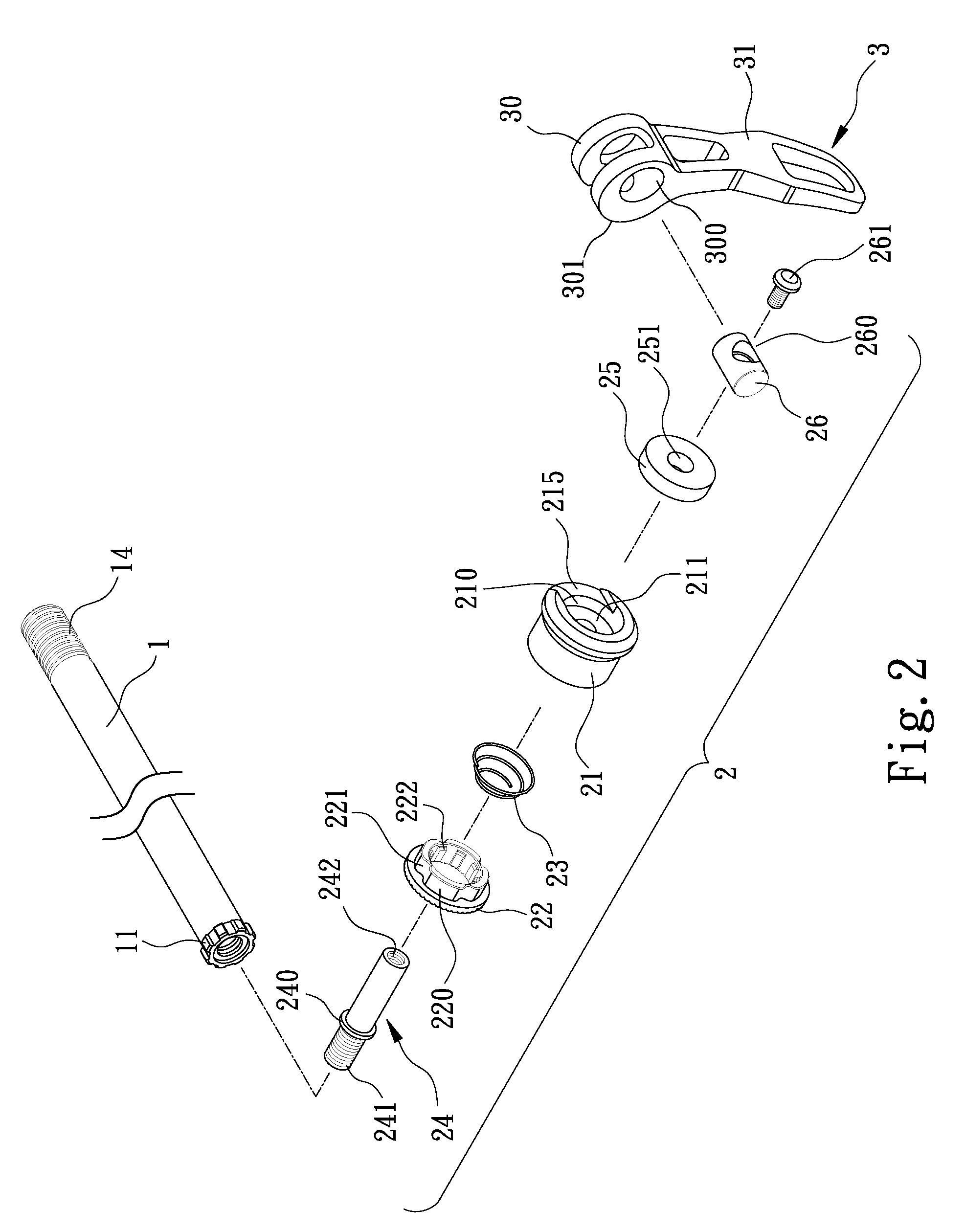
[0024]The quick-release device in accordance with the present invention comprises a shank (1), an engaging assembly (2) mounted to a first end of the shank (1) and a lever (3) pivotally connected to the engaging assembly (2).

[0025]The shank (1) includes an outer threaded portion (14) formed on a first end and a flange (11) radially extending from a second end thereof. A series of first teeth (110) is peripherally formed on the flange (11) and a through hole (10) is centrally and longitudinal...


PUM


Abstract

A quick-release device includes a shank and a flange radially extending from one end of the shank. A ring is sleeved on the shank and engaged to the flange. A sleeve is co-axially connected and engaged to the ring. A washer is received in the sleeve. A shaft is co-axially connected to the shank and sequentially extending through the ring, the sleeve and the washer. A pivot is transversely mounted to a distal end of the shaft and abutting the washer. A lever is pivotally mounted onto the pivot for selectively forcedly and inwardly pushing the washer and engaged to the sleeve.

Description

CROSS-REFERENCE TO RELATED APPLICATION[0001]This application is a continuation-in-part application of U.S. patent application Ser. No. 13 / 160,508, filed Jun. 15, 2011, and entitled “QUICK-RELEASE DEVICE”, now pending, the contents of which are included herein by reference.BACKGROUND OF THE INVENTION[0002]1. Field of the Invention[0003]The present invention relates to a quick-release device, and more particularly to a quick-release device that includes a lever selectively driving a tubular structure thereof for detaching the quick-release device when being released.[0004]2. Description of Related Art[0005]A conventional quick-release device in accordance with the prior art shown in FIGS. 5 and 6 is adapted to be mounted on a fork (4), wherein the fork (4) includes a tube (41) having a through hole (410) defined in a free end thereof to allow the quick-release device extending through the tube (41).[0006]The conventional quick-release device includes a shaft (5) extends through the th...

Claims


Application Information

Patent Timeline
Patent Type & Authority Patents(United States)
IPC IPC(8): B25G3/18
CPCB62K25/02B62K2206/00Y10T403/32442Y10T403/595
Inventor CHANG, CHIN-CHAO
Owner CHANG CHIN CHAO
Learn More