Servo minimum pressure valve

a technology of servo and valve body, which is applied in the direction of turbine/propulsion fuel valves, mechanical equipment, transportation and packaging, etc., can solve the problem that the fuel system may become unpredictabl

Active Publication Date: 2013-08-20
HAMILTON SUNDSTRAND CORP
View PDF16 Cites 4 Cited by
  • Summary
  • Abstract
  • Description
  • Claims
  • Application Information

AI Technical Summary

Benefits of technology

[0007]FIG. 1 schematically illustrates a perspective vi...

Problems solved by technology

Without consistent valve operation,...

Method used


Image

  • Servo minimum pressure valve
  • Servo minimum pressure valve
  • Servo minimum pressure valve

Examples


Embodiment Construction

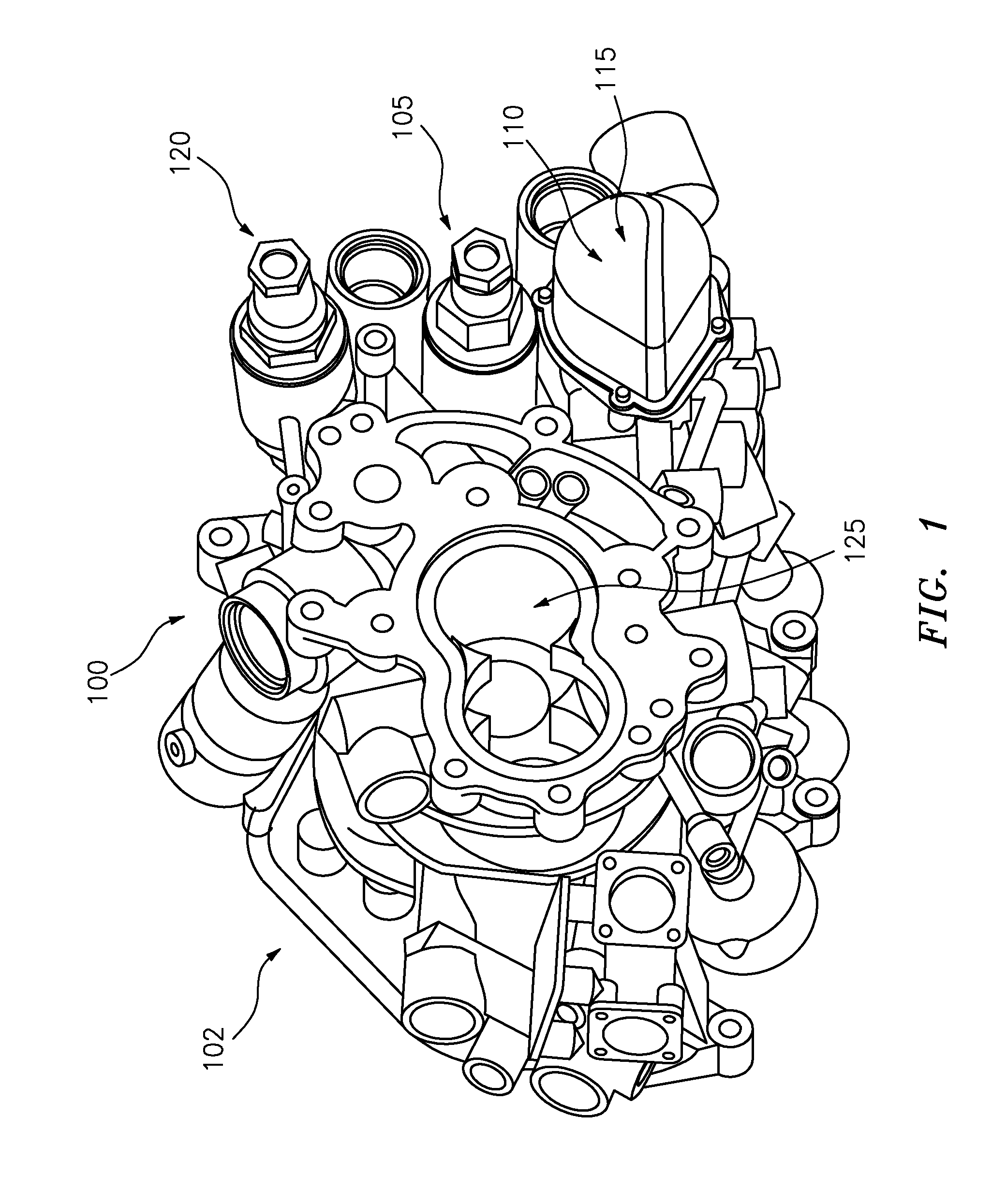
[0012]FIG. 1 schematically illustrates a perspective view of a fuel control housing portion 100 of a fuel control 102 for regulating fuel flow for systems such as aircraft gas turbine engines. In one embodiment, the fuel control housing portion 100 includes a pressure regulating valve section 105, a metering valve section 110, a containment housing section 115 that is generally adjacent to the metering valve section 110, and a servo minimum pressure valve section 120. Other valves, control and feedback features (not depicted) may also be included in the fuel control housing portion 100 or in another portion (not depicted) of the fuel control 102. For example, a separate servo pump may be included in the fuel control 102 to generate a servo pressure. Fuel flowing into the fuel control housing portion 100 is pressurized in a pump section 125. Pressurized flow is metered in metering valve section 110 before being output as a fuel burn flow at a metered pressure. The pressure regulating...


PUM


Abstract

A servo minimum pressure valve assembly includes a servo minimum pressure sleeve and a servo minimum pressure valve spool. The servo minimum pressure sleeve includes an inlet aperture, a first window set, a second window set, and a third window set. A ratio of an outlet window diameter of the first window set to an outlet window diameter of the second window set is between 2.34 and 2.65. The outlet window diameter of the second window set is greater than an outlet window diameter of the third window set. The servo minimum pressure valve spool is configured to move bi-directionally along a longitudinal axis of the servo minimum pressure valve sleeve. The servo minimum pressure valve spool includes a cylindrical portion to control a fluid flow between the inlet aperture of the servo minimum pressure sleeve and the first, second, and third window sets of the servo minimum pressure sleeve.

Description

BACKGROUND OF THE INVENTION[0001]The present invention is related to fuel flow control, and more specifically to a servo minimum pressure valve.[0002]Fuel flow control in systems such as gas turbines includes controlling and maintaining pressures within a fuel control housing of a fuel control. To control and maintain pressures within the fuel control housing, often the fuel flow is increased and decreased as well as diverted via a combination of control valves. A displacement pump pressurizes fuel prior to its metering and subsequent delivery to an engine. The displacement pump is typically sized to ensure an excess flow capacity at all possible operating conditions. The output of the pump is delivered to a fuel metering valve which, in conjunction with a bypassing, pressure regulating valve (PRV), meters the rate of fuel burn flow to the engine. The fuel control can also provide fluid pressure for actuators. Fluid pressure for the actuators is controlled and excess flow can be dis...

Claims


Application Information

Patent Timeline
IPC IPC(8): F16K11/07
CPCG05D16/10F02C7/232G05D16/024Y10T137/0502Y10T137/86734Y10T137/86799
Inventor RICKIS, AARON
Owner HAMILTON SUNDSTRAND CORP
Why Eureka
Try Eureka