Fixing device and image forming apparatus

a technology of fixing device and fixing belt, which is applied in the direction of electrographic process apparatus, instruments, optics, etc., can solve the problem that the heating efficiency of the fixing belt cannot be sufficiently improved

Inactive Publication Date: 2013-08-06
RICOH KK
View PDF24 Cites 0 Cited by
  • Summary
  • Abstract
  • Description
  • Claims
  • Application Information

AI Technical Summary

Benefits of technology

[0006]Accordingly, embodiments of the present invention may provide a novel and useful fixing device and image forming apparatus solving one or more of the problems discussed above.
[0007]More specifically, the embodiments of the present invention may provide a fixing device and an image forming apparatus whereby a warming-up time or a first printing time is short; bad fixing does not happen even if a process of the apparatus is made to speed up; heating efficiency of the fixing member is sufficiently high; and the likelihood of generating a problem where a fixing member makes sliding contact with a metal member so as to become worn at the time of operation of the image forming apparatus is reduced.

Problems solved by technology

In the fixing device discussed in, for example, Japanese Patent Application Publication No. 2008-158482, if a clearance amount (facing distance) between the fixing belt (fixing member) and the metal member is too large, heating efficiency of the fixing belt cannot be sufficiently improved.
If the clearance amount between the fixing belt and the metal member is too small, the fixing belt may make sliding contact with the metal member so as to become worn at the time of operation of the image forming apparatus.

Method used


Image

  • Fixing device and image forming apparatus
  • Fixing device and image forming apparatus
  • Fixing device and image forming apparatus

Examples


first embodiment

[0024]A first embodiment of the present invention is discussed in detail with reference to FIG. 1 through FIG. 8.

[0025]First, the overall configuration and operation of an image forming apparatus is discussed with reference to FIG. 1.

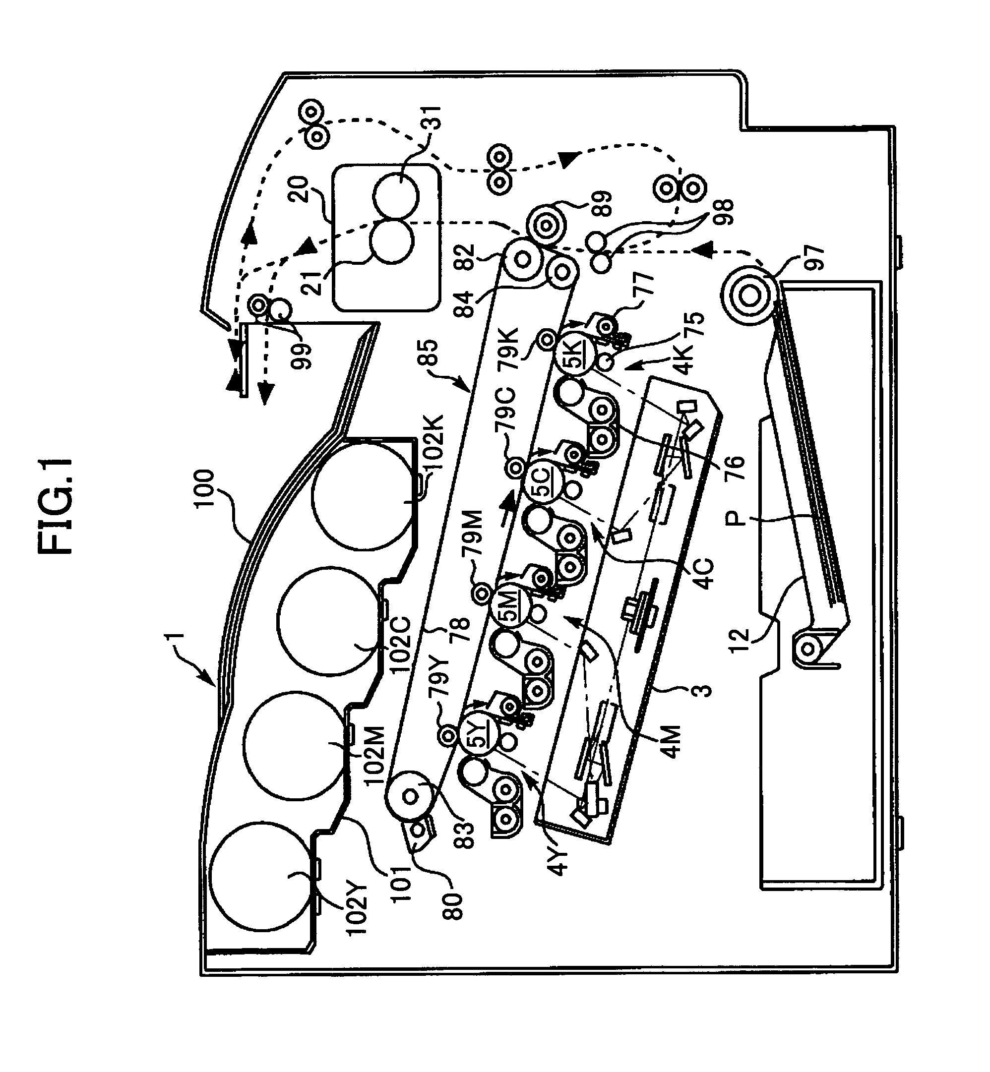
[0026]As shown in FIG. 1, an image forming apparatus 1 according to the first embodiment of the present invention is a tandem-type color printer. Four toner bottles 102Y, 102M, 102C, and 102K corresponding to colors yellow, magenta, cyan, and black, respectively, are removably (exchangeably) installed in a bottle housing portion 101 above the image forming apparatus main unit 1.

[0027]An intermediate transfer unit 85 is arranged below the bottle housing portion 101. Image forming portions 4Y, 4M, 4C, and 4K corresponding to colors yellow, magenta, cyan, and black are provided in a row arrangement so as to be facing an intermediate transfer belt 78 of the intermediate transfer unit 85.

[0028]Photosensitive drums 5Y, 5M, 5C, and 5K are arranged in the image...

second embodiment

[0115]A second embodiment of the present invention is discussed in details with reference to FIG. 9.

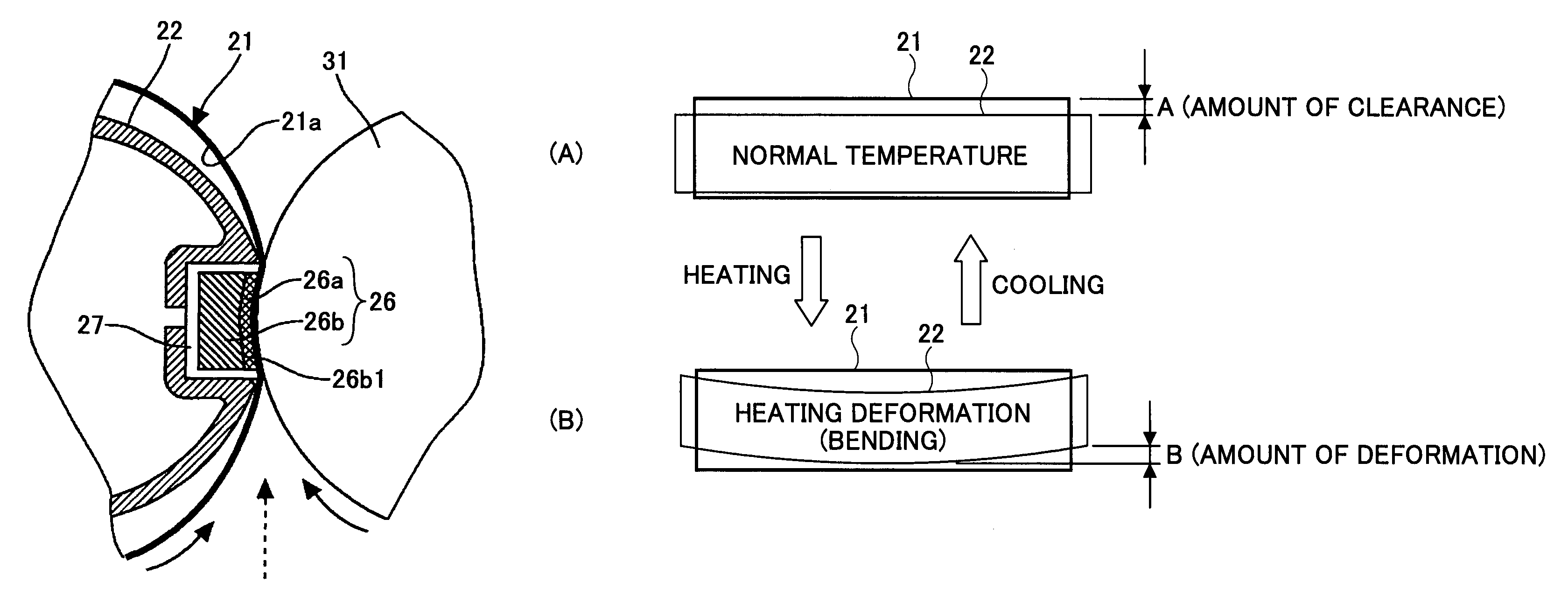
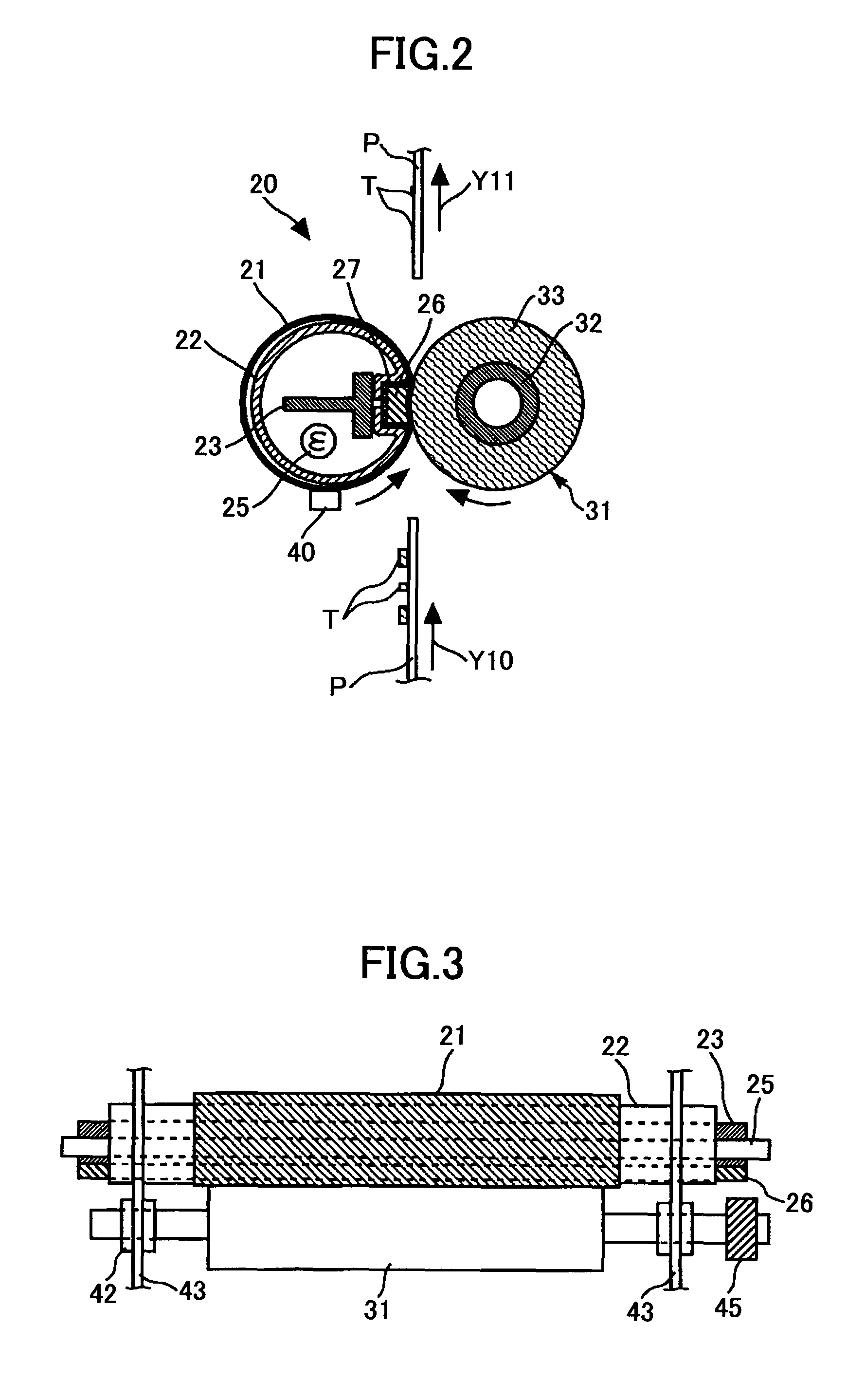
[0116]FIG. 9 is a structural view showing a fixing device of a second embodiment of the present invention. The fixing device of the second embodiment is different from the fixing device of the first embodiment in that the metal member 22 is heated by using electromagnetic induction in the fixing device of the second embodiment.

[0117]As shown in FIG. 9, the fixing device 20 of the second embodiment of the present invention, as well as that of the first embodiment of the present invention, includes the fixing belt 21, the fixating member 26, the metal member 22, the pressing roller 31, the adiabatic member 27, and others. In addition, in the fixing device 20 of the second embodiment of the present invention, as well as that of the first embodiment of the present invention, “A” is equal to or less than “Bmax.” and greater than “Bave” (“Bmax”≧“A”>“Bave”), where “A” represents an amount of...


PUM


Abstract

A fixing device includes a flexible endless fixing member; a metal member; and a pressing member. “A” is equal to or less than “Bmax” and greater than “Bave” (“Bmax”≧“A”>“Bave”), where “A” represents an amount of a clearance at the time of normal temperature between the fixing member and the metal member, “Bmax” represents a maximum amount of deformation generated in the metal member when heating is started by the heating member from a normal temperature state, and “Bave” represents an amount of stable deformation generated in the metal member when the temperature of the entire metal member becomes even.

Description

TECHNICAL FIELD[0001]The present invention generally relates to fixing devices and image forming apparatuses. More particularly, the present invention relates to an image forming apparatus such as a copier, a printer, a facsimile machine, a multi-function printer thereof or the like and a fixing device provided in the image forming apparatus.BACKGROUND ART[0002]Conventionally, a fixing device, used for an image forming apparatus such as a copier or printer, where a warming-up time or a first printing time is short and bad fixing may not happen even if a process of the apparatus is made to speed up has been known. See, for example, Japanese Patent Application Publication No. 2008-158482.[0003]More specifically, the fixing device discussed in, for example, Japanese Patent Application Publication No. 2008-158482, there are a fixing belt as a fixing member, a metal member as a facing member, a heater as a heating member, a pressing roller as a pressing member, and others. The metal memb...

Claims


Application Information

Patent Timeline
Patent Type & Authority Patents(United States)
IPC IPC(8): G03G15/00G03G15/20
CPCG03G15/2053G03G2215/2035G03G15/2028G03G15/2032G03G2215/20
Inventor SHINSHI, AKIRAISHIGAYA, YASUNORI
Owner RICOH KK
Why Eureka
Try Eureka