
Optical fiber telecommunication cable

a technology of optical fiber and telecommunications cables, applied in the field of optical fiber telecommunication cables, can solve the problems of buckling of the micromodules below, difficult access to optical fibers through metal tubes, and unwanted stresses of extracting fibers from buffer tubes

Active Publication Date: 2013-07-30
DRAKA COMTEQ BV
View PDF77 Cites 24 Cited by
  • Summary
  • Abstract
  • Description
  • Claims
  • Application Information

AI Technical Summary

Benefits of technology

The solution enables the extraction of optical fibers over long distances without sagging micromodules, reducing attenuation and mechanical strain, facilitating easy access and installation in multi-story buildings by using a greasy component as a lubricant and reinforcing elements for structural support.

Problems solved by technology

Although the buffer tubes can be extracted from the cable, extracting fibers from the buffer tubes would subject the optical fibers to unwanted stresses.
Although this publication does not describe the manner in which the fibers would be extracted during a dropping operation, access to the optical fibers through the metal tubes would be difficult.
This can cause buckling of the micromodules below and corresponding tension upon the micromodules above.
These effects can cause unwanted attenuation.
In addition, the optical fibers can be subjected to mechanical strains at the dropping points, thereby further increasing attenuation.

Method used


Image

  • Optical fiber telecommunication cable
  • Optical fiber telecommunication cable
  • Optical fiber telecommunication cable

Examples


Embodiment Construction

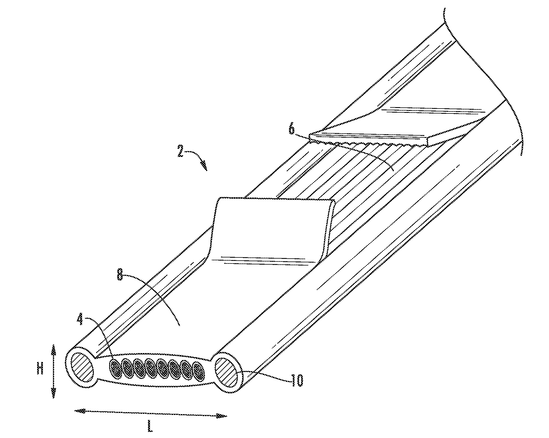
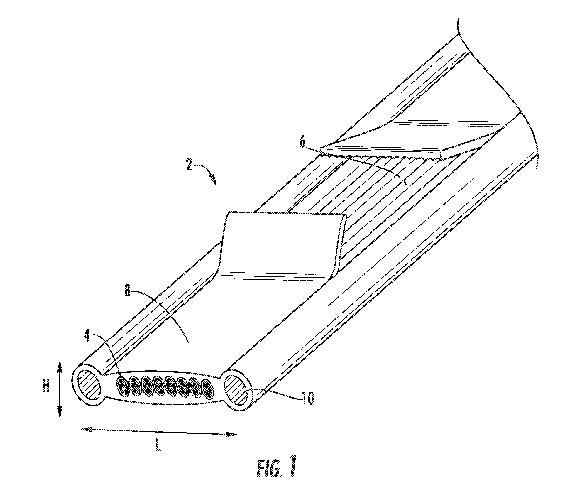
[0016]In one aspect, the invention embraces a flat optical fiber telecommunication cable (e.g., an indoor riser cable) that includes a plurality of optical-fiber micromodules in a side-by-side arrangement (i.e., parallel to one another in the form of a ribbon). The optical fibers contained within the micromodules not only are continuously accessible but also can be extracted from the flat cable without requiring the extraction of the corresponding micromodules.

[0017]As will be appreciated by those having ordinary skill in the art, a flat cable is used herein to refer to a cable in which the optical-fiber micromodules are positioned side-by-side. Unlike cylindrical cables, flat cables facilitate access to each constituent micromodule. Unlike other flat cables, the present flat cable employs optical-fiber micromodules that permit the ready extraction of the optical fibers from the micromodules without requiring sharp cutting tools.

[0018]Each micromodule of the present cable includes a...


PUM


Abstract

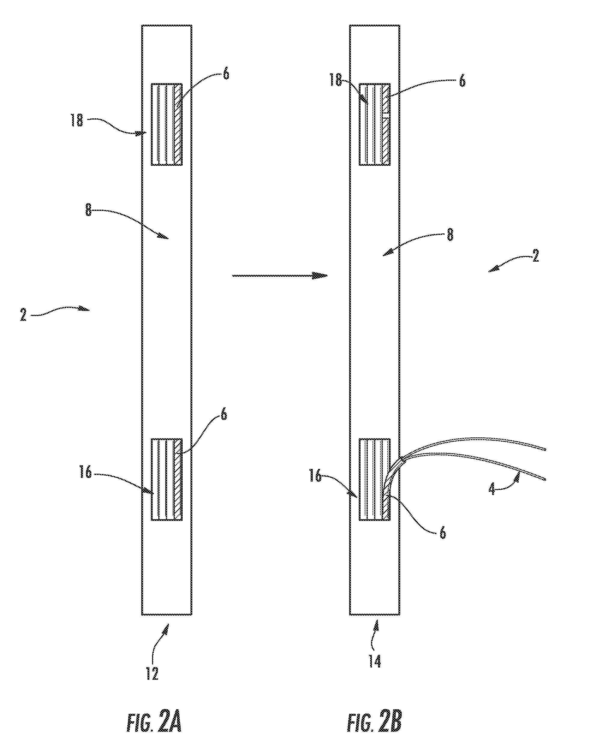
The invention relates to a flat telecommunication cable in which optical fibers are positioned within micromodules. The micromodules are coupled to a surrounding, ribbon-like cable jacket, thereby preventing the micromodules from sagging within the cable during vertical installations. The invention also relates to a method of extracting optical fibers from such a cable.

Description

CROSS-REFERENCE TO PRIORITY APPLICATION[0001]This application claims the benefit of pending French Application No. 08 / 02656 for “Optical Fiber Telecommunication Cable” (filed May 16, 2008, at the French Patent Office), which is hereby incorporated by reference in its entirety.FIELD OF THE INVENTION[0002]The present invention relates to a telecommunication cable in which a plurality of optical fibers is grouped in a plurality of micromodules. The present invention also relates to method for extracting the optical fibers from such a telecommunication cable.BACKGROUND OF THE INVENTION[0003]Optical fiber cables having optical-fiber modules are known from French Patent No. 2,665,266 (and its counterpart U.S. Pat. No. 5,155,789) and French Patent No. 2,706,218 (and its counterpart U.S. Pat. No. 5,671,312). Each of these patents is each hereby incorporated by reference in its entirety.[0004]A conventional telecommunication cable can include a plurality of optical fibers that are grouped in...

Claims


Application Information

Patent Timeline
Patent Type & Authority Patents(United States)
IPC IPC(8): G02B6/44
CPCG02B6/4403G02B6/4495G02B6/4475G02B6/4431
Inventor TATAT, OLIVIER
Owner DRAKA COMTEQ BV
Learn More