
Image inspection apparatus

a technology of image inspection and apparatus, applied in the field of image inspection apparatus, can solve the problems of difficult formation of the same shape with high reproducibility, significant misalignment of an image, etc., and achieve the effect of ensuring the matching position

Active Publication Date: 2013-07-30
HITACHI HIGH-TECH CORP
View PDF17 Cites 13 Cited by
  • Summary
  • Abstract
  • Description
  • Claims
  • Application Information

AI Technical Summary

Benefits of technology

[0026]The present invention allows an adequate matching position to be provided even in an image with a distorted pattern shape and a variation in edge intensity.

Problems solved by technology

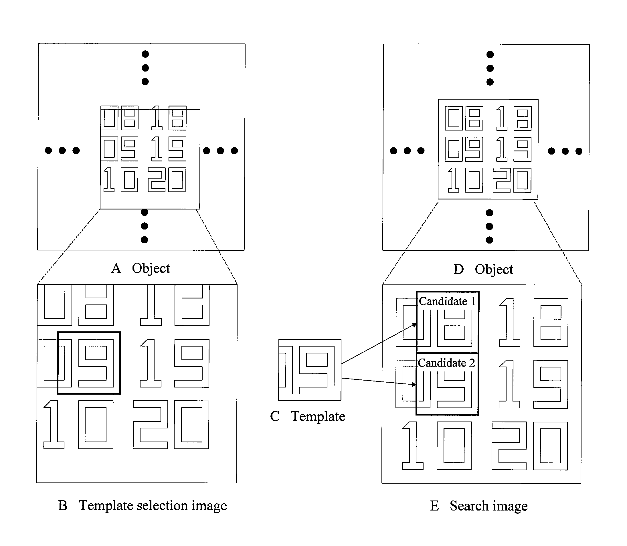
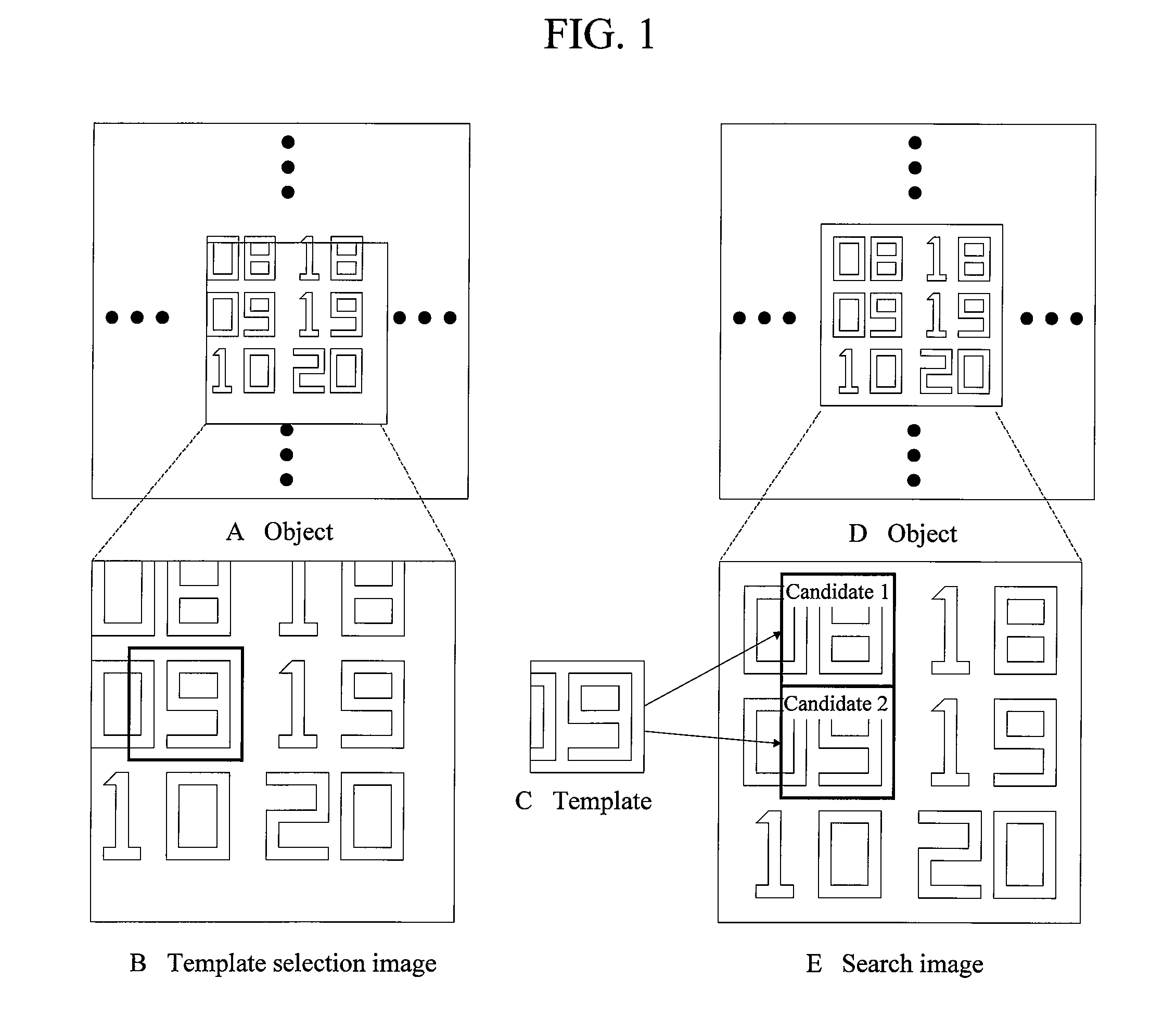
However, the positioning accuracy for the stage may lead to a significant misalignment on an image taken by an electron microscope at a high magnification.
This is because the improved micromachining of semiconductors has made formation of the same shape with high reproducibility difficult.

Method used


Image

  • Image inspection apparatus
  • Image inspection apparatus
  • Image inspection apparatus

Examples


first embodiment

[0062](1) First Embodiment

[0063]FIG. 5 is a diagram schematically showing the configuration of an inspection apparatus according to a first embodiment of the present invention. FIG. 5 does not show the configuration of an electron microscope. Provided that the inspection apparatus 50 can store images acquired by the electron microscope, as search images, the electron microscope need not be connected directly to the inspection apparatus 50.

[0064]The inspection apparatus 50 includes a processing section 51 formed of, for example, an MPU or a CPU to carry out various processes, a storage section 52 which stores the results of processes carried out by the processing section 51, a RAM (Random Access Memory) 53 which temporarily stores data, a ROM (Read Only Memory) 54 which stores process programs and parameters for the processing section 51, and a display apparatus 55 which displays inspection results and images.

[0065]The processing section 51 includes an edge image generation section 5...

second embodiment

[0111](2) Second Embodiment

[0112]FIG. 23 is a diagram schematically showing the configuration of an inspection apparatus 230 according to a second embodiment of the present invention. Like FIG. 5, FIG. 23 does not show the configuration of an electron microscope.

[0113]The inspection apparatus 230 includes a processing section 231 formed of, for example, an MPU or a CPU to carry out various processes, a storage section 232 which stores the results of processes carried out by the processing section 231, a RAM (Random Access Memory) 233 which, for example, temporarily stores data, a ROM (Read Only Memory) 234 which stores process programs and parameters for the processing section 231, and a display apparatus 235 which displays inspection results and images.

[0114]The processing section 231 includes an edge image generation section 2311 which generates edge images of a template image and a search image, a template matching section 2312 which performs template matching, a centroid distanc...


PUM


Abstract

The present invention provides a unified template matching technique which allows an adequate matching position to be provided even in an image with a distorted pattern shape and a variation in edge intensity. A correlation value contribution rate map is created for the vicinity of each of top candidate positions obtained by applying a centroid distance filter to a normalized correlation map resulting from template matching. A corrected intensity image is created from the correlation value contribution rate maps. Luminance correction is performed based on the corrected intensity image. Local matching is performed again on the vicinity of each candidate position. The candidates are then re-sorted based on candidate positions and correlation values newly obtained. Thus, even in an image with a distorted pattern shape and a variation in edge intensity, an adequate matching position can be provided in a unified manner.

Description

[0001]This application is the U.S. National Phase under 35 U.S.C. §371 of International Application No. PCT / JP2009 / 057662, filed on Apr. 16, 2009, which in turn claims the benefit of Japanese Application No. 2008-106847, filed on Apr. 16, 2008, the disclosures of which Applications are incorporated by reference herein.TECHNICAL FIELD[0002]The present invention relates to an image inspection apparatus, and for example, to an apparatus such as a semiconductor inspection apparatus which performs template matching for image inspection.BACKGROUND ART[0003]A technique for searching for a particular shape (template) provided in a target image has been widely used as template matching (see Non-Patent Document 1).[0004]In measurement of a pattern on a semiconductor wafer using a scanning electron microscope, the template matching is also performed in order to determine a measurement position. Alignment with the measurement position is roughly carried out by moving a stage with the wafer load...

Claims


Application Information

Patent Timeline
Patent Type & Authority Patents(United States)
IPC IPC(8): G06K9/62G06K9/00
CPCG06K9/6203G06T7/0044G06T7/60G06T2207/10061G06T2207/30148G06T7/74G06V10/7515
Inventor ABE, YUICHIIKEDA, MITSUJISATO, YOSHIMICHITOYODA, YASUTAKA
Owner HITACHI HIGH-TECH CORP
Learn More