Refractive index distribution measuring method and refractive index distribution measuring apparatus
a technology of refractive index and measuring method, which is applied in the direction of optical apparatus testing, applications, instruments, etc., can solve the problems of time-consuming adjustment and different refractive index distribution, and achieve the effect of fast and highly precise measuremen
- Summary
- Abstract
- Description
- Claims
- Application Information
AI Technical Summary
Benefits of technology
Problems solved by technology
Method used
Image
Examples
first embodiment
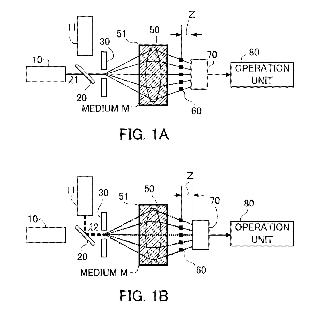
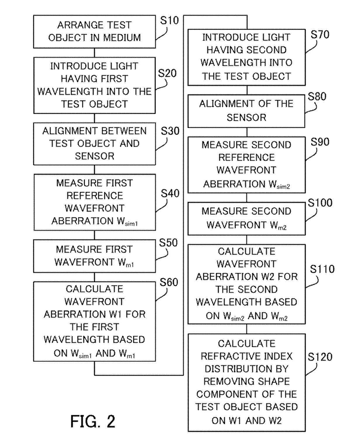
[0015]A description will now be given of a refractive index distribution measuring apparatus that executes a refractive index distribution measuring method according to a first embodiment. The refractive index distribution measuring apparatus measures a transmitted wavefront of a test object by immersing the object in a medium (M) having a refractive index different from that of the test object and by introducing two types of reference beams, such as light of a first wavelength and light of a second wavelength, into the object. The refractive index distribution measuring apparatus then calculates a refractive index distribution of the test object utilizing a measurement result of the transmitted wavefront. The test object is a lens (optical element) having a positive power.
[0016]FIG. 1 is a block diagram of a Talbot interferometer as a measuring unit configured to measure the transmitted wavefront of the test object 50 utilizing two beams having different wavelengths. A side surface...
second embodiment
[0074]In a second embodiment, a measuring unit other than the interferometer is used for measurements of a test object having a negative power. Those elements in this embodiment, which are the corresponding elements in the first embodiment, will be designated by the same reference numerals.
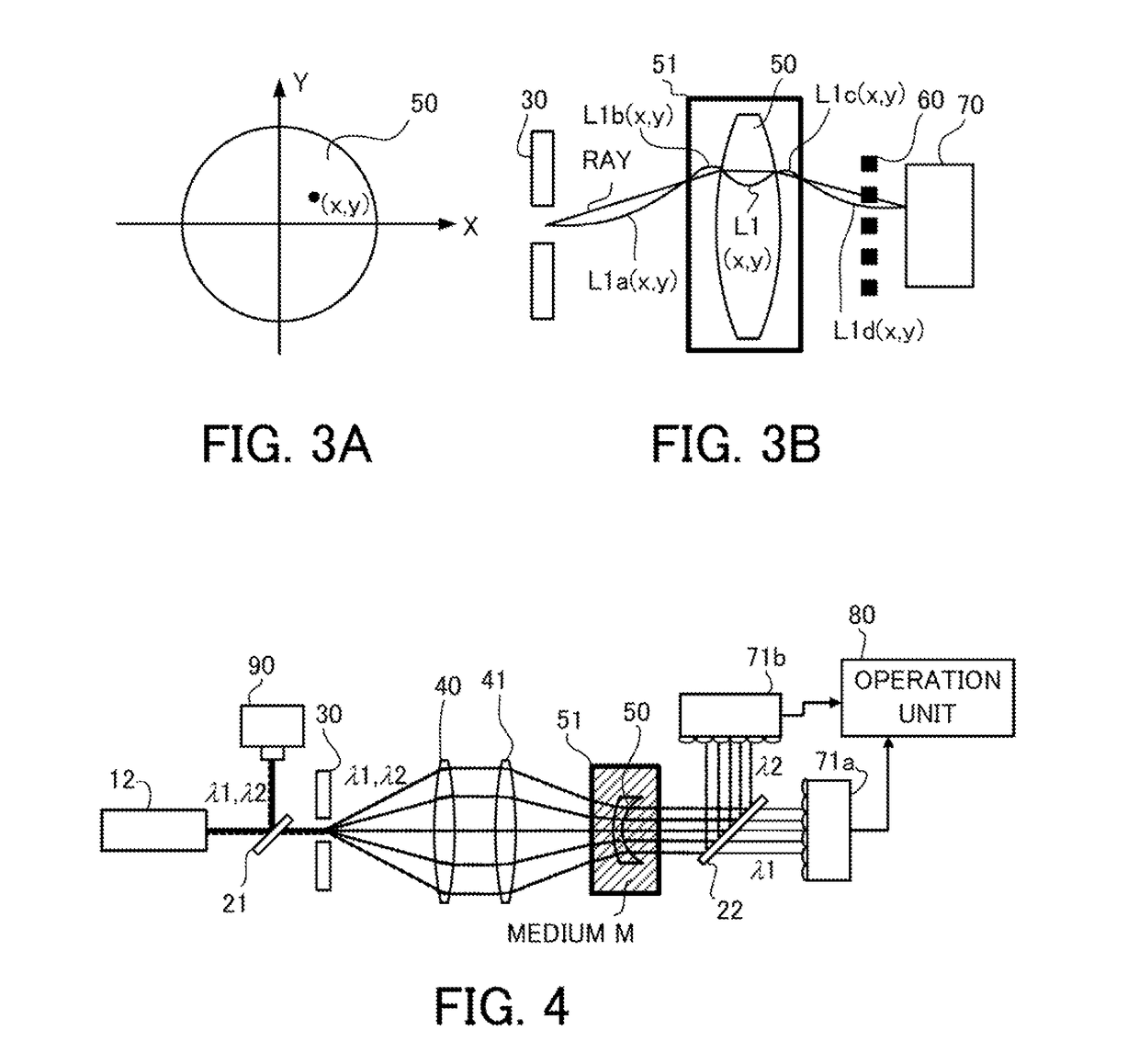
[0075]FIG. 4 is a block diagram of a measuring apparatus of this embodiment. The test object 50 is a lens (optical element) having a negative power. The medium M filled in a space around the test object 50 is, for example, water (although FIG. 4 illustrates it as a medium).
[0076]A light source 12 is configured to simultaneously emit beams of two types of wavelengths, such as a multimode oscillating laser (e.g., a fundamental wave and a second harmonic of a YAG laser) or a combination of a broadband light source (e.g., a Supercontinuum light source) and a specific wavelength-selective filter. Shack-Hartman sensors 71a, 71b are used to measure transmitted wavefronts.
[0077]The light having the first ...
third embodiment
[0087]A third embodiment discusses a refractive index distribution measuring apparatus that can omit decentering, inclining, and adjusting a position in the optical axis direction of the test object, which are necessary for the first and second embodiments. Those elements in this embodiment, which are the same as corresponding elements in the first and second embodiments, are designated by the same reference numerals.
[0088]FIG. 5 is a block diagram of a measuring apparatus of this embodiment. The test object 50 is a lens (optical element) having a negative power. The medium M filled in a space around the test object 50 is, for example, oil. A light source 13 is a light source configured to emit beams of two or more wavelengths at proper timings, such as a wavelength variable laser (e.g., a semiconductor laser) or a combination of a broadband light source (e.g., a Halogen lamp) and a specific wavelength-selective filter. A Talbot interferometer is used to measure a transmitted wavefr...
PUM
| Property | Measurement | Unit |
|---|---|---|
| diameter | aaaaa | aaaaa |
| diameter | aaaaa | aaaaa |
| refractive index | aaaaa | aaaaa |
Abstract
Description
Claims
Application Information
 - R&D
- Intellectual Property
- Life Sciences
- Materials
- Tech Scout
- Unparalleled Data Quality
- Higher Quality Content
- 60% Fewer Hallucinations
Browse by: Latest US Patents, China's latest patents, Technical Efficacy Thesaurus, Application Domain, Technology Topic, Popular Technical Reports.
© 2025 PatSnap. All rights reserved.Legal|Privacy policy|Modern Slavery Act Transparency Statement|Sitemap|About US| Contact US: help@patsnap.com


