
Wire guiding system

a technology of guiding wire and wire, which is applied in the field of guiding wire systems to achieve the effects of preventing incorrect installation, reducing manufacturing costs, and reducing friction

Active Publication Date: 2013-06-04
AWDS TECH
View PDF246 Cites 3 Cited by
  • Summary
  • Abstract
  • Description
  • Claims
  • Application Information

AI Technical Summary

Benefits of technology

The invention is a liner or guide that helps supply welding wire to a welding torch with less friction and allows the wire to be pushed through from the feeder towards the torch. This is achieved with a wire guiding liner with multiple roll holders that are displaceable with respect to each other. The rolls in the liner ensure that there is small friction only, and the limited angular displaceability of the roll holders with respect to each other ensures that the front end of the wire can be easily pushed through the liner without getting stuck. The liner does not require an outer tube and can be installed in a small diameter cable hose. The adjacent roll holders are connected by a defined pivot axis, which prevents bending, stretching, or compressing of the liner material and increases its lifetime.

Problems solved by technology

If the material of the liner is subjected to bending stress when being moved, the material becoming brittle due to UV radiation results in breakage.

Method used


Image

  • Wire guiding system
  • Wire guiding system
  • Wire guiding system

Examples


first embodiment

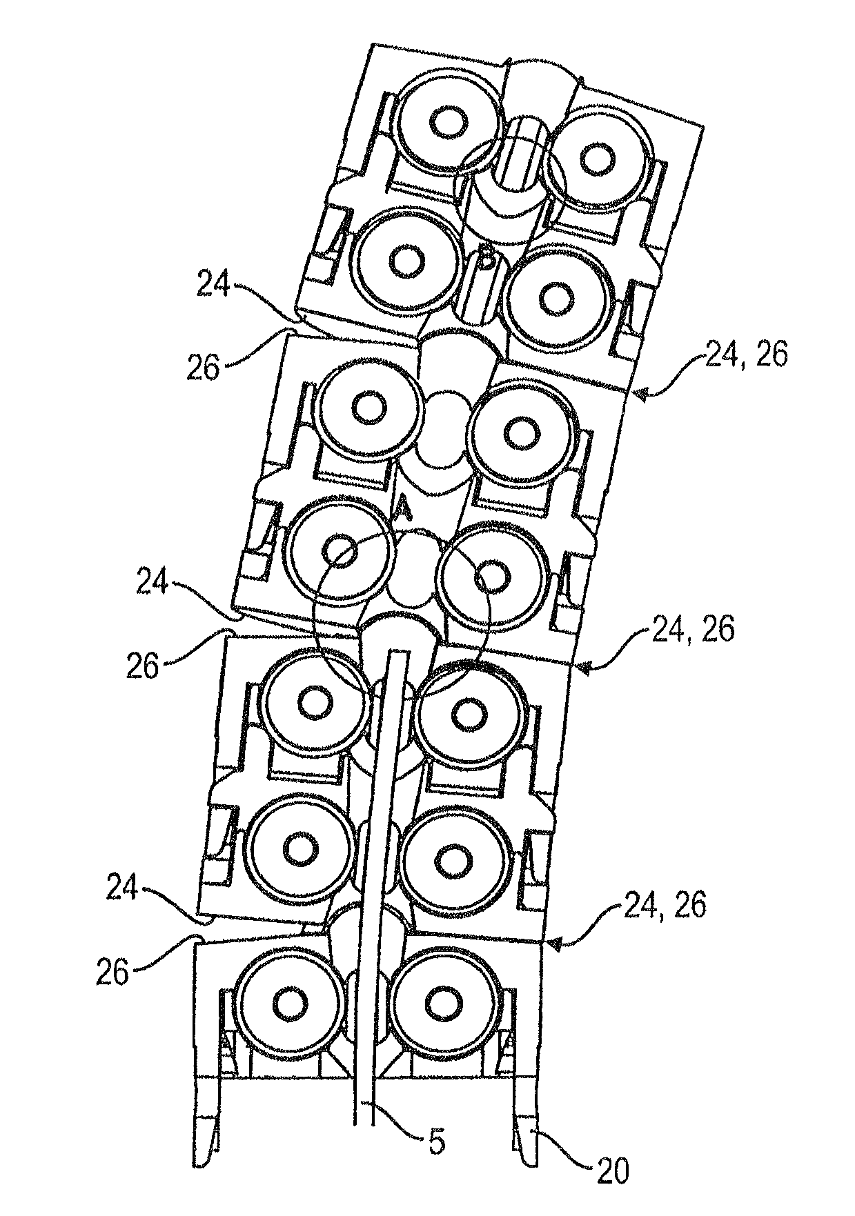
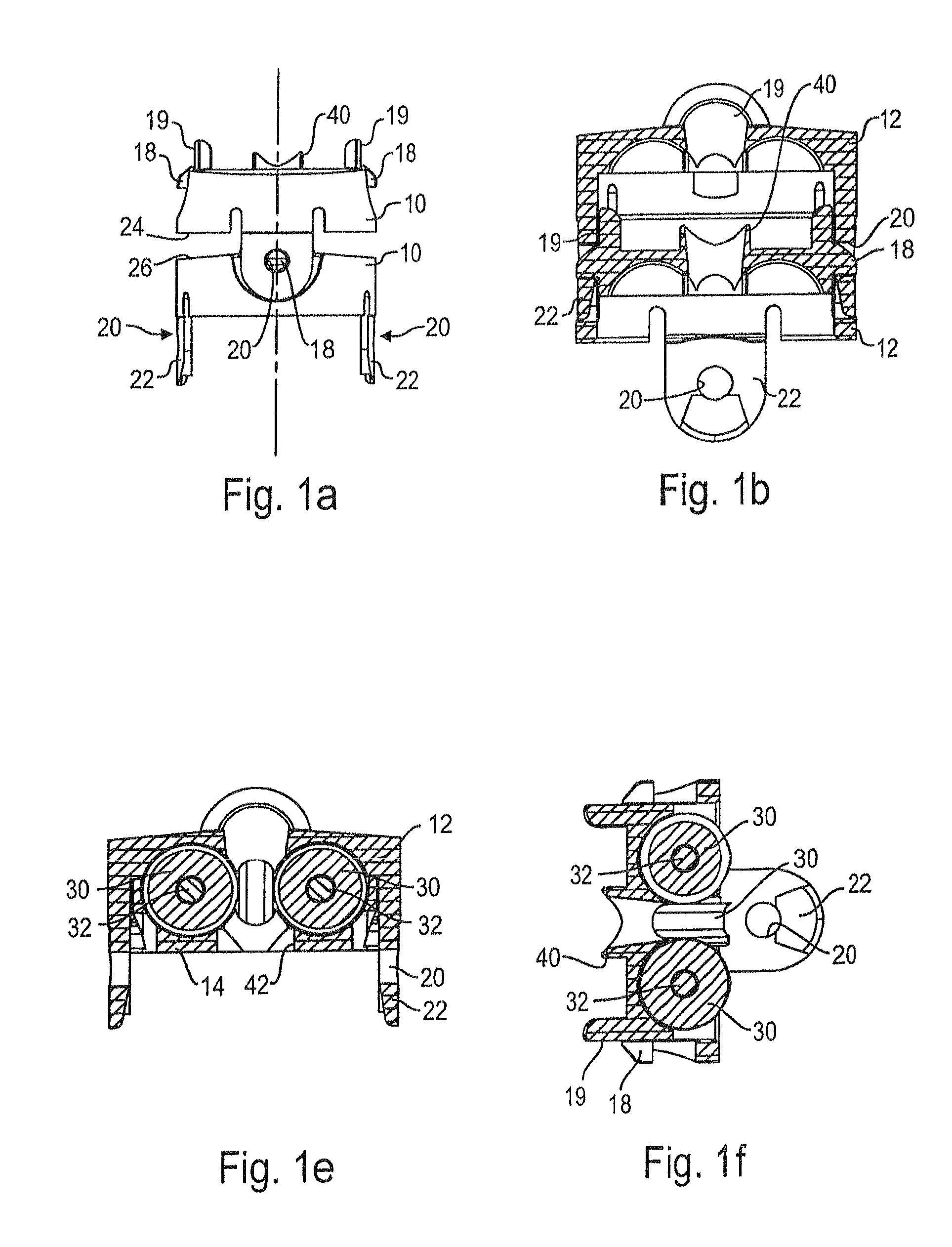
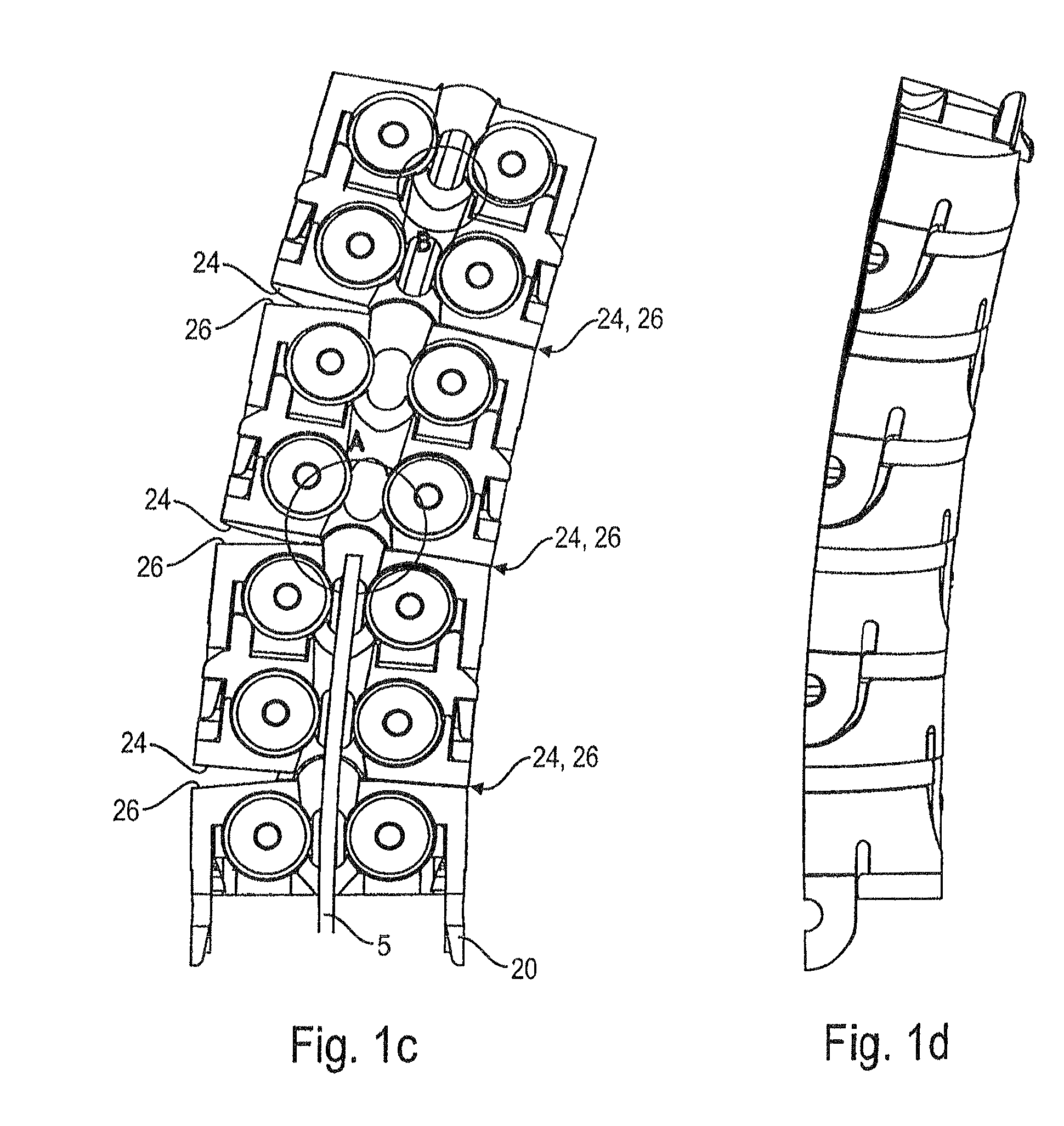
[0030]In FIG. 1, the invention is shown. The wire guide is to guide a welding wire 5 and consists of a plurality of individual roll holders 10 which each comprise a body 12 and an insert 14.

[0031]The body has, seen in an axial direction, two pivot pins 18 at one side, and two pivot pin accommodation openings 20 at the other side. The openings 20 are formed in holding lugs 22, and the pins protrude from guiding surfaces 19. Both the pins and the openings are arranged diametrically opposite each other. In other words, both pins are arranged on one and the same diameter, and the two openings are arranged also on one diameter, with the diameter at which the pins are arranged expending perpendicularly with respect to the diameter at which the openings are arranged.

[0032]As can be seen in FIG. 1b, the holding lugs 22 are supported by the guiding surfaces 19 when the pins 18 of a first roll holder 10 engage in the openings 20 of an adjacent roll holder 10. Each pin is provided with a chamf...

third embodiment

[0054]The roll holders of both the second and the third embodiment are finally arranged in the interior of a tube or like sheath in order to prevent the welding wire from picking up dirt.

[0055]In FIGS. 7a and 7b, an additional feature is shown which can be used with the first and / or last roll holder of the welding wire guide. The respective roll holder is provided with a clip connection 70 allowing to clamp a short portion of a conventional metal wire guide 9. This allows to fit the new liner to conventional systems.

[0056]In summary, basic idea is to form a liner comparable to a flexible hose with small diameter, having in its interior a plurality of rolling elements close to one another. This provides for small friction while at the same time guaranteeing that the wire, even if the liner is bent, does not touch any supporting parts but is guided only by means of the rolling elements. The liner works bi-directional, which is an advantage over the prior art systems.


PUM

PropertyMeasurementUnit
angleaaaaaaaaaa
flexibleaaaaaaaaaa
elasticaaaaaaaaaa

Abstract

A wire guiding liner, in particular welding wire liner, has a plurality of roll holders which are displaceable with respect to each other, each roll holder holding a plurality of rolls. The angular displaceability of a roll holder with respect to the adjacent roll holder is limited such that when the wire is fed through the liner, it always touches exclusively on the rolls even when the liner is bent to its maximum curve, such that the wire while being inserted always hits the next roll at an angle that will push it towards and maintain it guided at the center of the liner.

Description

BACKGROUND OF THE INVENTION[0001]The invention relates to a system for guiding wire, in particular welding wire.[0002]A welding wire guide is used to supply welding wire from a wire feeder to a welding torch. Usually, a closed metal tube is used, comparable to the sheath of a Bowden cable. Such liner is flexible and has a small diameter, allowing it to be mounted on a welding torch. Another advantage is that the welding wire can be easily pushed through the liner from the feeder towards the torch without the risk that the front end of the wire gets stuck somewhere in the middle. However, significant friction occurs when the welding wire is moved through the liner during use. As a consequence, the conventional liner after it has been in use for some time becomes clogged with lubricant and metal particles with considerable wire feeding and welding problems and be replaced frequently, resulting in significant down-time of the respective welding robot and unwanted interruptions of produ...

Claims


Application Information

Patent Timeline
Patent Type & Authority Patents(United States)
IPC IPC(8): B23K9/133B23K9/12B65H57/14
CPCB23K9/1336B65H57/12B65H57/14H02G3/0475
Inventor GELMETTI, CARLOCORRADINI, FILIPPO
Owner AWDS TECH
Learn More