
Magnetic reciprocating pump

a reciprocating pump and magnetic technology, applied in the field of pumps, can solve the problems of difficult disassembly if the pump needed cleaning or maintenance, the check valve is a particularly troublesome component, and the design of the past pump did not take full advantage of the direct magnetic driv

Inactive Publication Date: 2013-05-28
SIELC TECH
View PDF11 Cites 17 Cited by
  • Summary
  • Abstract
  • Description
  • Claims
  • Application Information

AI Technical Summary

Benefits of technology

The present invention provides a pump with the following features: minimum of parts, easy disassembly for cleaning or repair, and reassembly. The pump can be made in different sizes and deliver a predetermined measure of fluid. Additionally, the pump does not require seals that wear out by frictionally engaging an opposed surface.

Problems solved by technology

While having direct plunger drive capability, these past pump designs did not take full advantage of the direct magnetic drive.
They were still complex mechanisms, they still required check valves to prevent backflow, and they were difficult to disassemble if they required cleaning or maintenance.
Check valves are an especially troublesome component, since they have a tendency to leak or sometimes stick after a long idle period.
In addition, check valves are usually not reversible, allowing fluid to flow in only one direction.
In addition, the material from which check valves are constructed, namely, springs, balls, and the like, are incompatible with many fluids that are being moved through the pump.

Method used


Image

  • Magnetic reciprocating pump
  • Magnetic reciprocating pump
  • Magnetic reciprocating pump

Examples


Embodiment Construction

[0035]While the present invention is susceptible of embodiment in many different forms, there are shown in the drawings and will be described herein in detail specific embodiments thereof with the understanding that the present disclosure is to be considered as an exemplification of the principles of the invention and is not intended to limit the invention to the specific embodiments illustrated.

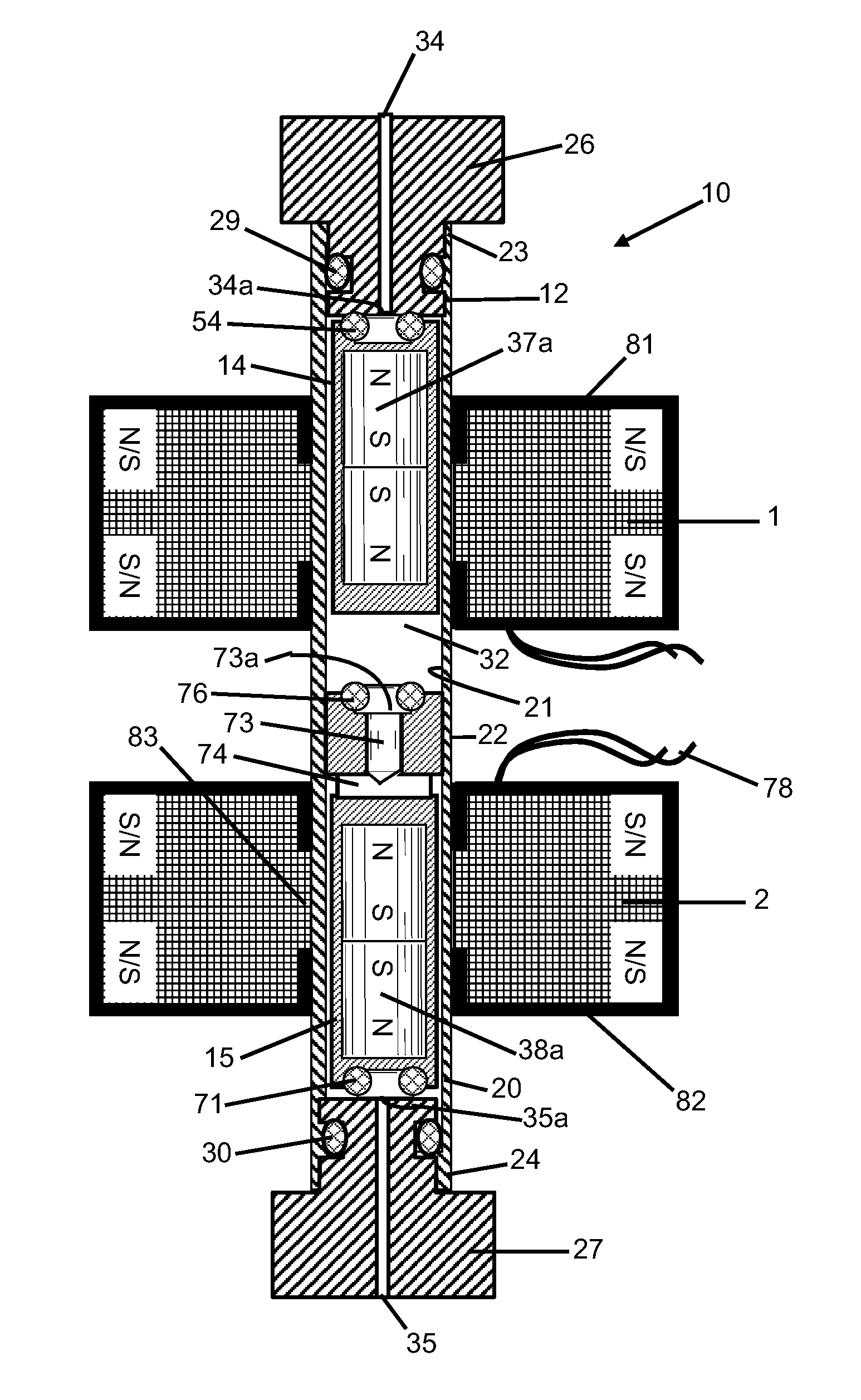
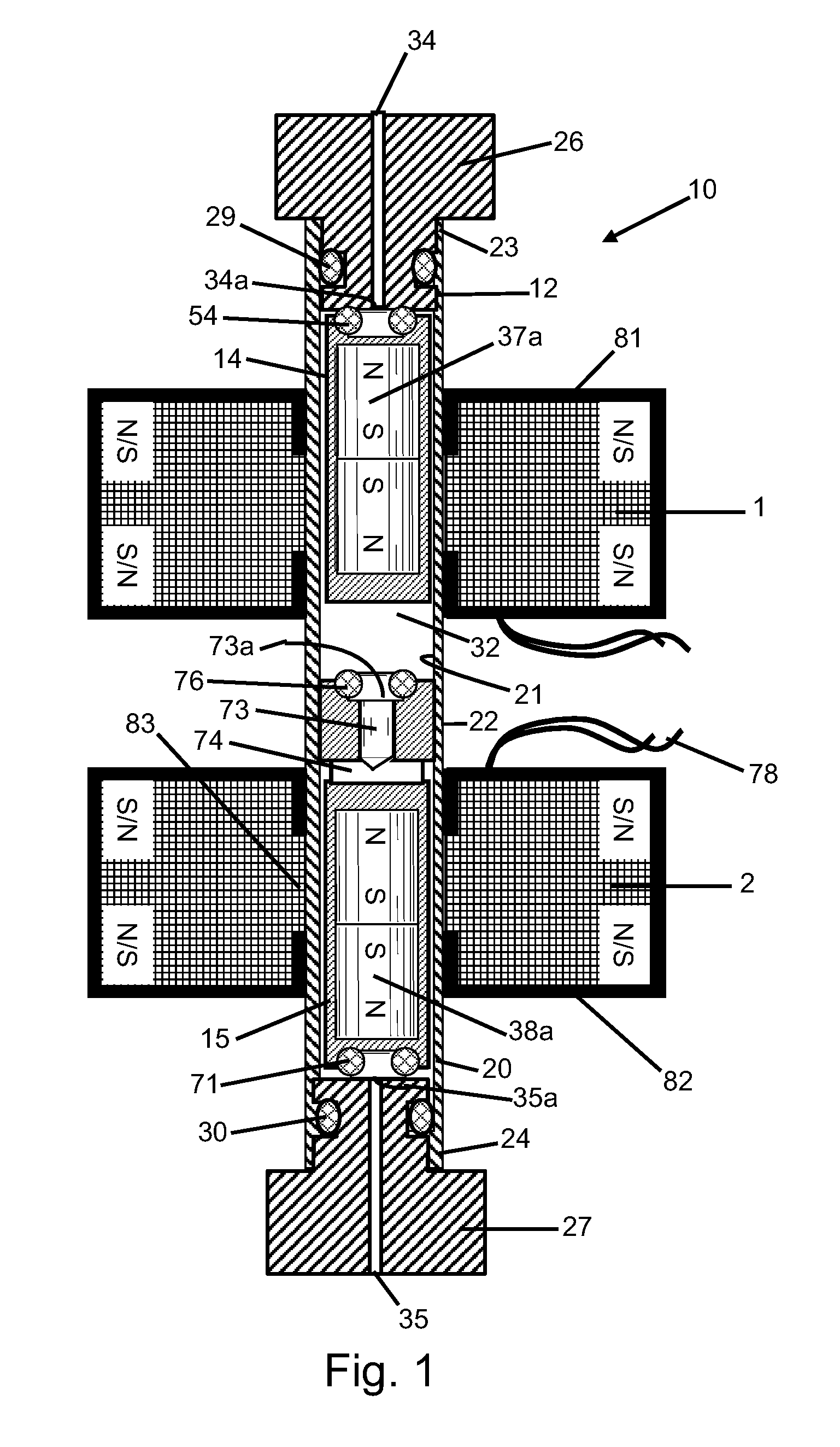
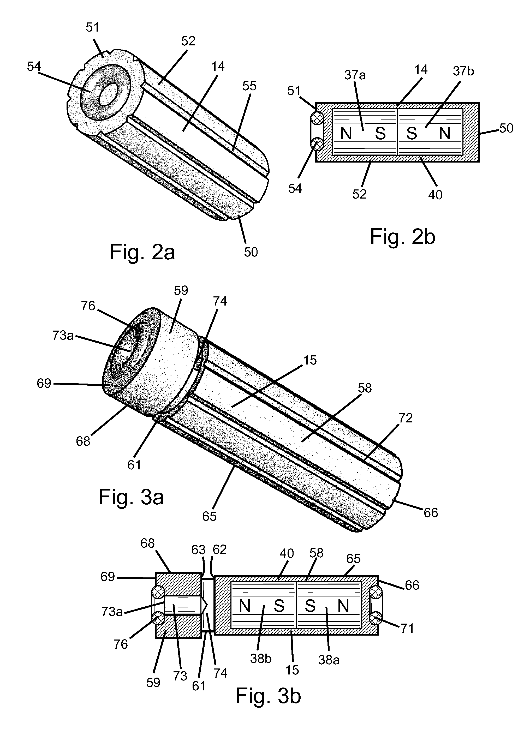
[0036]Referring to the drawings in greater detail, FIG. 1 shows an exemplary embodiment of a magnetic reciprocating pump, generally designated 10, constructed in accordance with the teachings of the present invention. The magnetic pump is seen to include an elongate tube 12, a pair of sliding, generally cylindrical, magnetic armatures or plungers 14 and 15 positioned end-to-end within the tube 12, and a pair of coils 1 and 2.

[0037]The tube 12 includes a side wall 20 with a relatively smooth inner surface 21, an outer surface 22, and upper and lower ends 23 and 24. Upper and lower end caps 26...


PUM


Abstract

A magnetic reciprocating pump includes a tube having ends defining intake and discharge ports, first and second magnetic plungers axially aligned within the tube of corresponding cross section for reciprocation therewithin, and a plurality of longitudinally spaced coils circumscribing the tube for driving the plungers axially when electrically energized. A gap is defined between the plungers so that the first plunger is slidable between one tube end and the second plunger and the second plunger is slidable between the other tube end and the first plunger. The first plunger closes one port when moved thereagainst and has a peripheral flow path permitting flow when moved away. The second plunger closes the other port when moved thereagainst and has an outer peripheral flow path and a communicating inner axial flow path permitting flow when moved away. The plungers when moved together close the second plunger axial flow path.

Description

BACKGROUND OF THE INVENTION[0001]1. Technical Field[0002]The present invention relates to a pump and, more particularly, to a reciprocating electromagnetic type pump.[0003]2. Background Art[0004]Typically, electrically driven reciprocating pumps include an electric motor, a motion translation means, and a pumping element of some kind. To make the motor work, a magnetic field is generated by the motor coils and this magnetic field creates tangential forces to turn the motor's rotor.[0005]There have been many attempts in the past to eliminate the electric motor by applying magnetic forces to drive a pump plunger directly. Examples of these designs are shown in Hirabayashi et al. U.S. Pat. No. 5,472,323 issued Dec. 5, 1995 and Olson U.S. Pat. No. 7,288,085 issued Oct. 30, 2007. By employing such designs, many mechanical components can be eliminated from the pump system, including bearings, sliding seals, and rotors.[0006]While having direct plunger drive capability, these past pump des...

Claims


Application Information

Patent Timeline
Patent Type & Authority Patents(United States)
IPC IPC(8): F04B17/04
CPCF04B17/04
Inventor ZELECHONOK, YURY
Owner SIELC TECH
Learn More