
Method for operating object between terminals and terminal using the method

a technology of operating object and terminal, applied in the direction of instruments, computing, electric digital data processing, etc., can solve the problems of one party operating, 50% discount of display efficiency, and severe reduction of efficiency, so as to improve the efficiency of cooperation between two computers spaced by a viewing distance

Inactive Publication Date: 2013-05-21
LENOVO (BEIJING) LTD
View PDF39 Cites 2 Cited by
  • Summary
  • Abstract
  • Description
  • Claims
  • Application Information

AI Technical Summary

Benefits of technology

This approach allows cursors to freely roam between screens, improving cooperation efficiency by enabling simultaneous control and operation of both computers, with each terminal handling its respective display content, thus enhancing collaborative computing.

Problems solved by technology

Since the desktop of the latter is under a complete control and thus cannot implement any other task, the efficiency is severely reduced.
Besides, the same screen content is displayed on both of the computers, resulting in a 50% discount of display efficiency.
The disadvantages are apparent, that is, only one party can operate at any moment, and only the desktop of the controlled party can be viewed.
Thus, the method is high in cost and inconvenient in use.
Further, the two computer systems cannot be controlled at the same time, since the method is a time division one, that is, one period is for communication mode where operation is made on the second terminal, and the other period is for non-communication mode where operation is made on only the host computer.
Apparently, such method has no contribution to the increase in the efficiency of cooperative computation.
This method also has obvious drawbacks, that is, when operating with SYNERGY technique, the other computers can be controlled by only the keyboard and the mouse of the master computer, thereby inhibiting the cooperation of and multiple computers by multiple persons.

Method used


Image

  • Method for operating object between terminals and terminal using the method
  • Method for operating object between terminals and terminal using the method
  • Method for operating object between terminals and terminal using the method

Examples


Embodiment Construction

[0032]Hereafter, a detailed description is given to the preferred embodiment of the present invention with reference to the figures, throughout which like elements are denoted by like reference symbols or numbers. In the following description, the details of any known function or configuration will not be repeated, otherwise they may obscure the subject of the present invention.

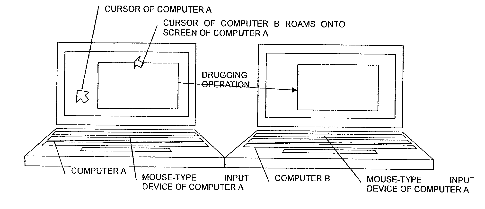
[0033]According to an embodiment of the present invention, two computer, computer A and computer B, are arranged in parallel. Each of the two computers A and B has a screen, a keyboard, a mouse and other components required for the normal operation of the computer, such as CPU, memory, hard disk, peripheral devices, etc. The two computers are connected via a network and spaced from each other only by a short distance so that they can be used by one person.

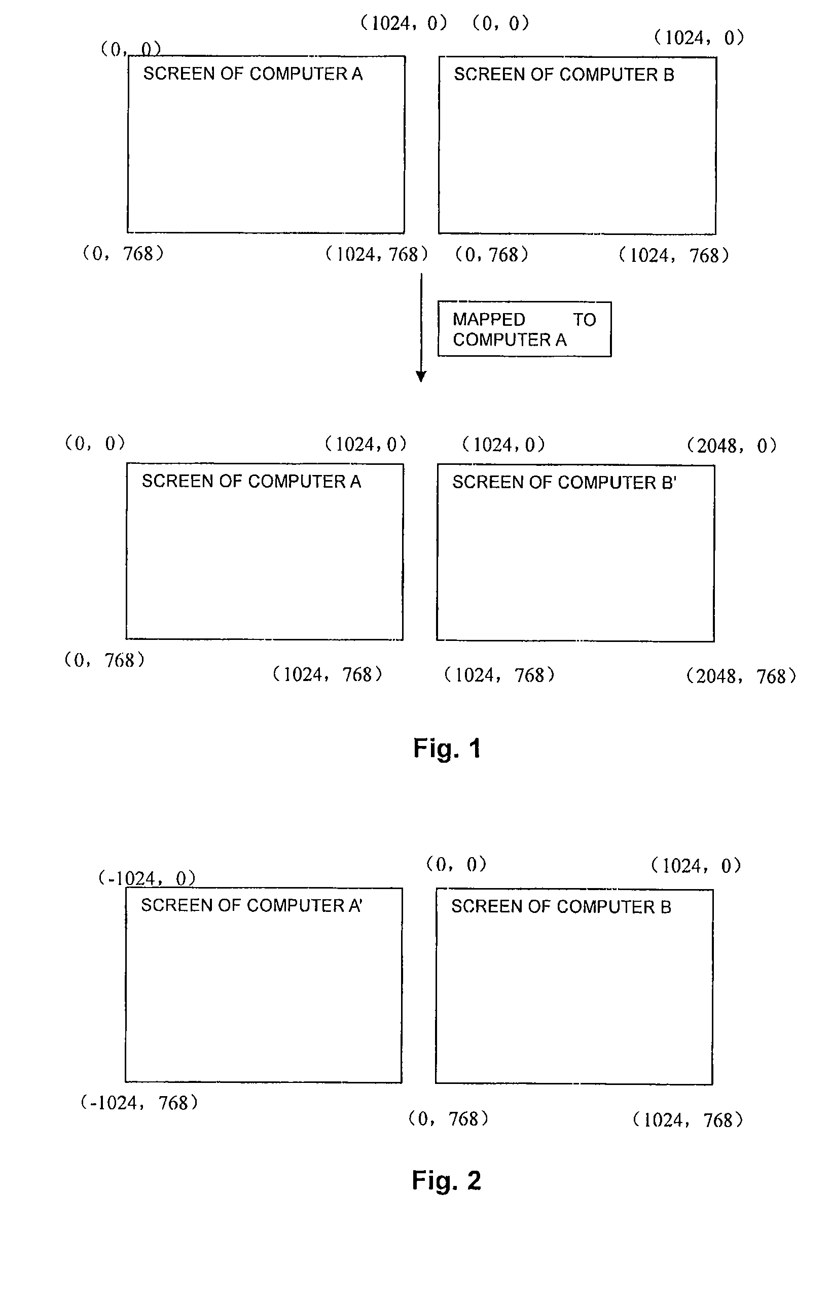
[0034]In the embodiment of the present invention, each of computer A and computer B is installed with a virtual extended screen drive for extending the scre...


PUM


Abstract

A method for operating an object between a first terminal and a second terminal. The display space of one of the first and second terminals is extended to the other terminal. One of the first and second terminals intercepts an event associated with the object occurring in the terminal so as to obtain the position of the object, informs the other terminal of the position of the object, and redraws the object on the screen of the other terminal based on the received position.

Description

BACKGROUND OF THE INVENTION[0001]1. Field of Invention[0002]The present invention relates to mutual display extension, cooperation and sharing among a plurality of terminals, in particular to a method for operating an object, such as a cursor, between two terminals as well as a terminal using the method, which can improve the efficiency of cooperation between two terminals spaced by a viewing distance.[0003]2. Description of the Related Prior Art[0004]Currently, to share information, two computers may extend their display parts mutually while cooperating with each other, especially when the two computers cooperate in computation within a viewing distance. In some of the existing solutions, a remote control method is adopted for the two computers, where one of the two computers performs control and desktop sharing on the screen of the other. Since the desktop of the latter is under a complete control and thus cannot implement any other task, the efficiency is severely reduced. Beside...

Claims


Application Information

Patent Timeline
Patent Type & Authority Patents(United States)
IPC IPC(8): G09G5/00
CPCG06F3/1423G06F3/1454G09G5/14G06F3/1446G09G5/08
Inventor LI, ZHONGQING
Owner LENOVO (BEIJING) LTD
Learn More