
Correction information calculating device, image processing apparatus, image display system, and image correcting method including detection of positional relationship of diagrams inside photographed images

a technology of image processing apparatus and image information, which is applied in the direction of static indicating devices, picture reproducers using projection devices, instruments, etc., can solve the problems of inability to perform extreme cases, process cannot be performed in extreme cases, and the correspondence relationship between the characteristic points projected onto the photographed image and the characteristic points that are projected, etc., to achieve high precision and reduce the burden of users

Inactive Publication Date: 2013-05-21
SEIKO EPSON CORP
View PDF4 Cites 6 Cited by
  • Summary
  • Abstract
  • Description
  • Claims
  • Application Information

AI Technical Summary

Benefits of technology

This approach enables precise acquisition of correspondence relationships between projected and surface characteristic points, minimizing user burden and improving the accuracy of image correction without requiring extensive user input, thus enhancing the precision and efficiency of image distortion correction.

Problems solved by technology

In performing the above-described process, it may be difficult to precisely specify the correspondence relationship between the characteristic points projected onto the photographed image and the projected characteristic points depending on the number or the shape of the characteristic points.
When the specifying of the correspondence relationship fails, the process needs to be retried, and the process cannot be performed in an extreme case.
In a case where a measurement pattern including a plurality of characteristic points is used, a case where diagrams representing the characteristic points are all the same, or the like, considerable effort and time are necessary for searching for the characteristic points as designated targets, whereby a considerable burden is placed on the user.
In addition, the user may easily incorrectly recognize the characteristic points as the designated targets, and there is a concern about a decrease in the degree of robustness of the process.

Method used


Image

  • Correction information calculating device, image processing apparatus, image display system, and image correcting method including detection of positional relationship of diagrams inside photographed images
  • Correction information calculating device, image processing apparatus, image display system, and image correcting method including detection of positional relationship of diagrams inside photographed images
  • Correction information calculating device, image processing apparatus, image display system, and image correcting method including detection of positional relationship of diagrams inside photographed images

Examples


Embodiment Construction

[0037]Hereinafter, embodiments of the invention will be described with reference to the accompanying drawings. In the drawings referred to, in order to represent characteristic parts to be easily understood, the size and the scale of a structure may be differently shown in the figures. In addition, to the same constituent elements, the same reference numeral is assigned, and detailed description thereof may be omitted.

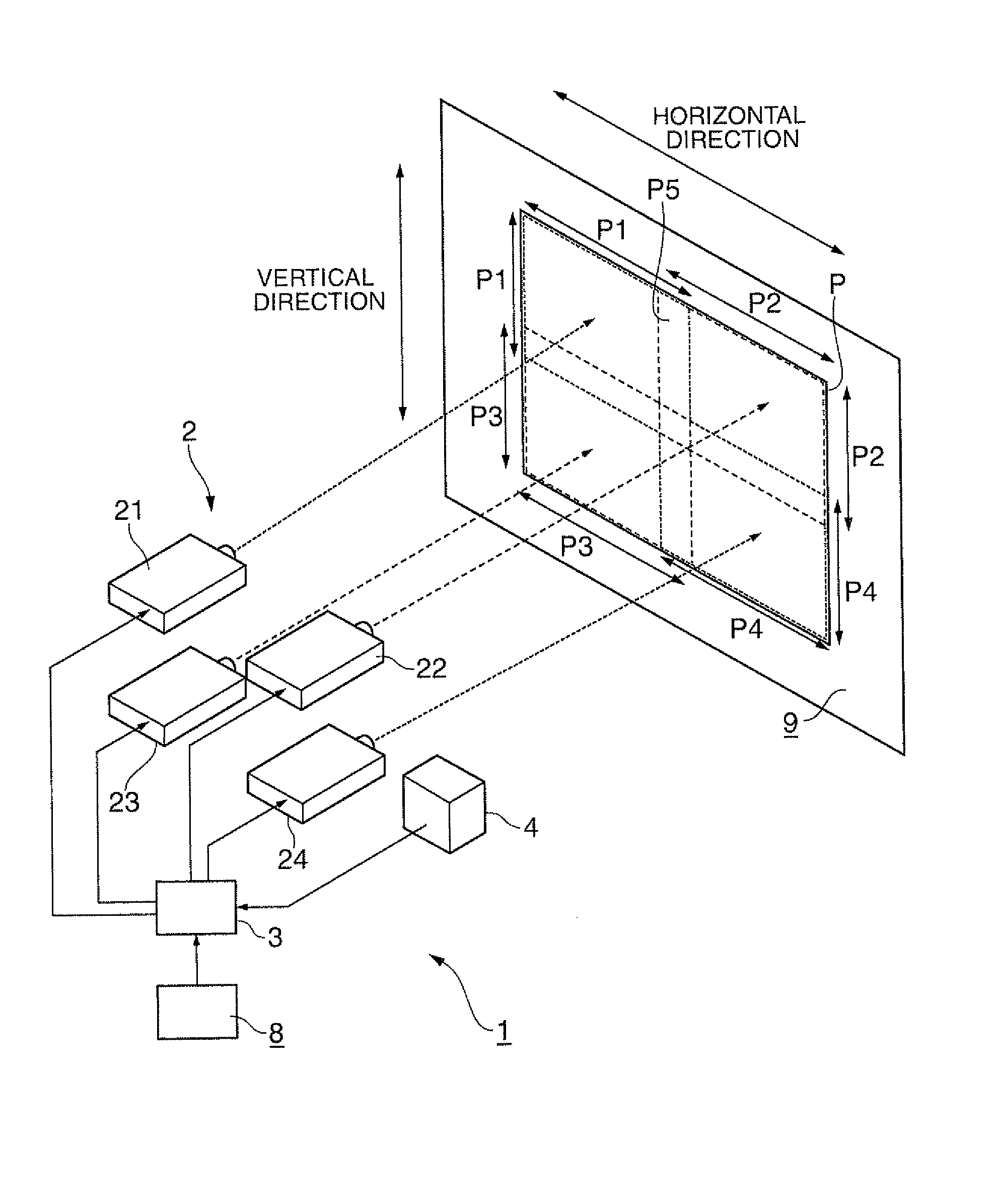
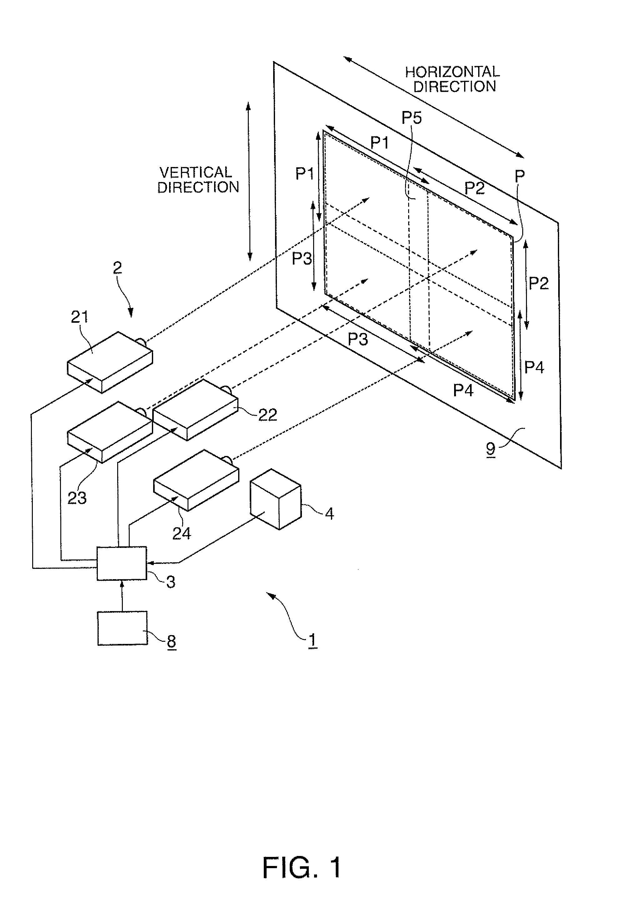
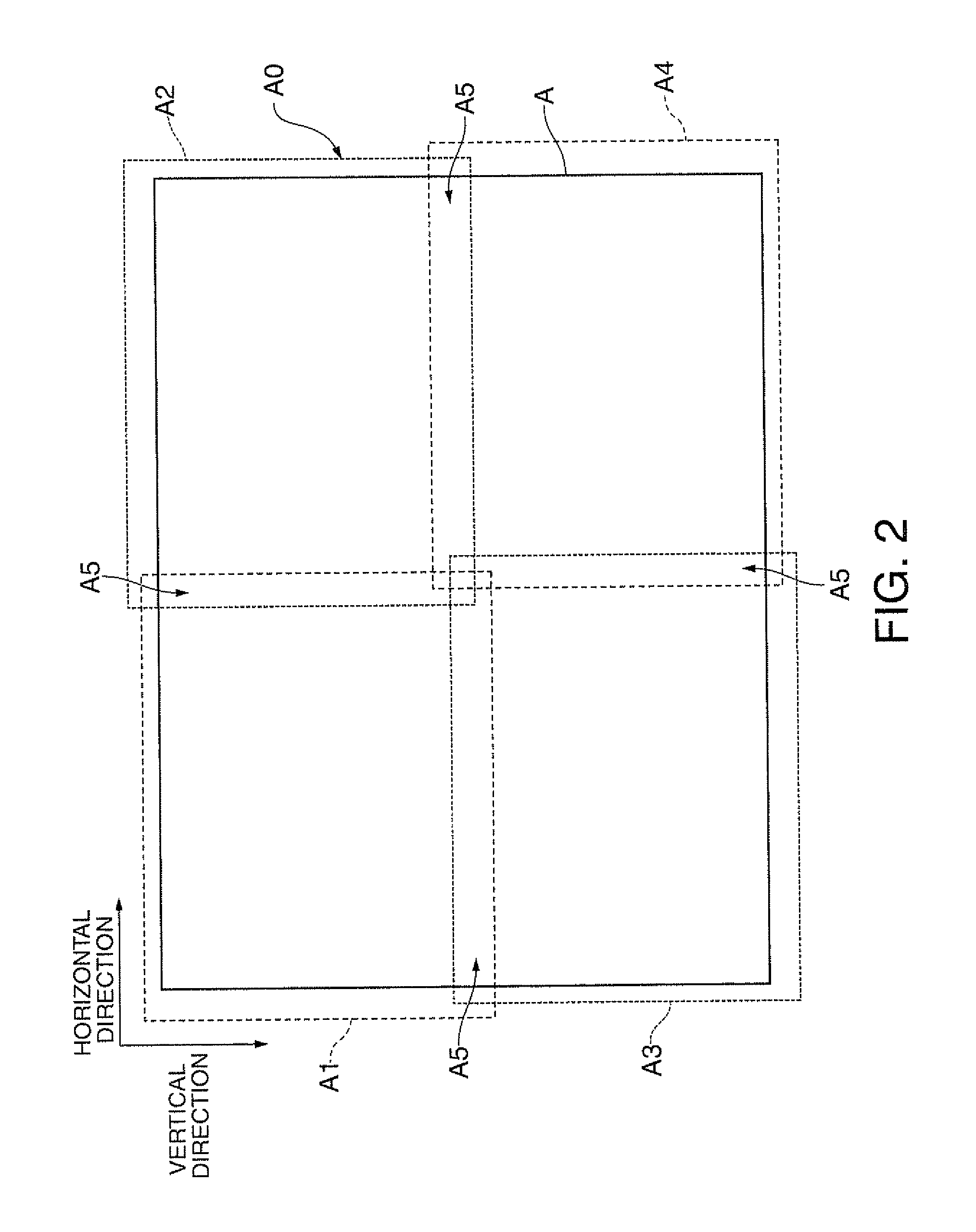
[0038]FIG. 1 is a conceptual diagram of an image display system according to an embodiment of the invention. FIG. 2 is an explanatory diagram showing the relationship between an image projected onto a projection surface and a projection area.

[0039]As shown in FIG. 1, the image display system 1 includes a plurality of projectors 2, an image processing apparatus 3, and a photographing device 4. The image display system 1 projects a content image P, for example, represented by image data input from a signal source 8 onto a projection surface 9 such as a screen or a wall b...


PUM


Abstract

A correction information calculating device includes: a position information acquiring unit that acquires position information representing a position corresponding to a first diagram located inside a first photographed image; a second diagram position detecting unit that detects a position of a second diagram, that is different from the first diagram in at least one of a shape and a size, inside a second photographed image; and a correction information calculating unit that calculates correction information representing a correspondence relationship between a position of a pixel on the projection surface and a position of a pixel of an image forming element of a projector by comparing the position of the second diagram inside the second photographed image that is detected by the second diagram position detecting unit and the position of the second diagram on an original data of the second measurement image.

Description

BACKGROUND[0001]1. Technical Field[0002]The present invention relates to a correction information calculating device, an image processing apparatus, an image display system, and an image correcting method.[0003]2. Related Art[0004]Generally, as one example of an image display device, a projector is known. Projectors have advantages such as ease of installation and the ability to display a big screen image. The projectors are used for displaying an image on a planar or curved projection surface. In addition, there are cases where projectors are used for displaying one image as the entirety of a plurality of partial images by projecting the partial images from a plurality of projectors. Recently, an image correcting method for correcting the distortion of images on the projection surface or a difference between relative positions of a plurality of partial images is proposed.[0005]In the above-described image correcting method, for example, the following process is performed. First, a ...

Claims


Application Information

Patent Timeline
Patent Type & Authority Patents(United States)
IPC IPC(8): H01L27/00
CPCH04N9/31H04N9/3194H04N9/3185H04N9/3147
Inventor FURUI, SHIKI
Owner SEIKO EPSON CORP
Learn More