
Electronic phantom and method for electronically controlling a phantom for a quantitative ultrasound device

a quantitative ultrasound and electronic control technology, applied in the field of medical diagnostic systems, can solve the problems of poor accuracy of simulation, and typical rubbery materials of materials with good bua characteristics

Inactive Publication Date: 2013-05-14
GENERAL ELECTRIC CO
View PDF13 Cites 0 Cited by
  • Summary
  • Abstract
  • Description
  • Claims
  • Application Information

AI Technical Summary

Benefits of technology

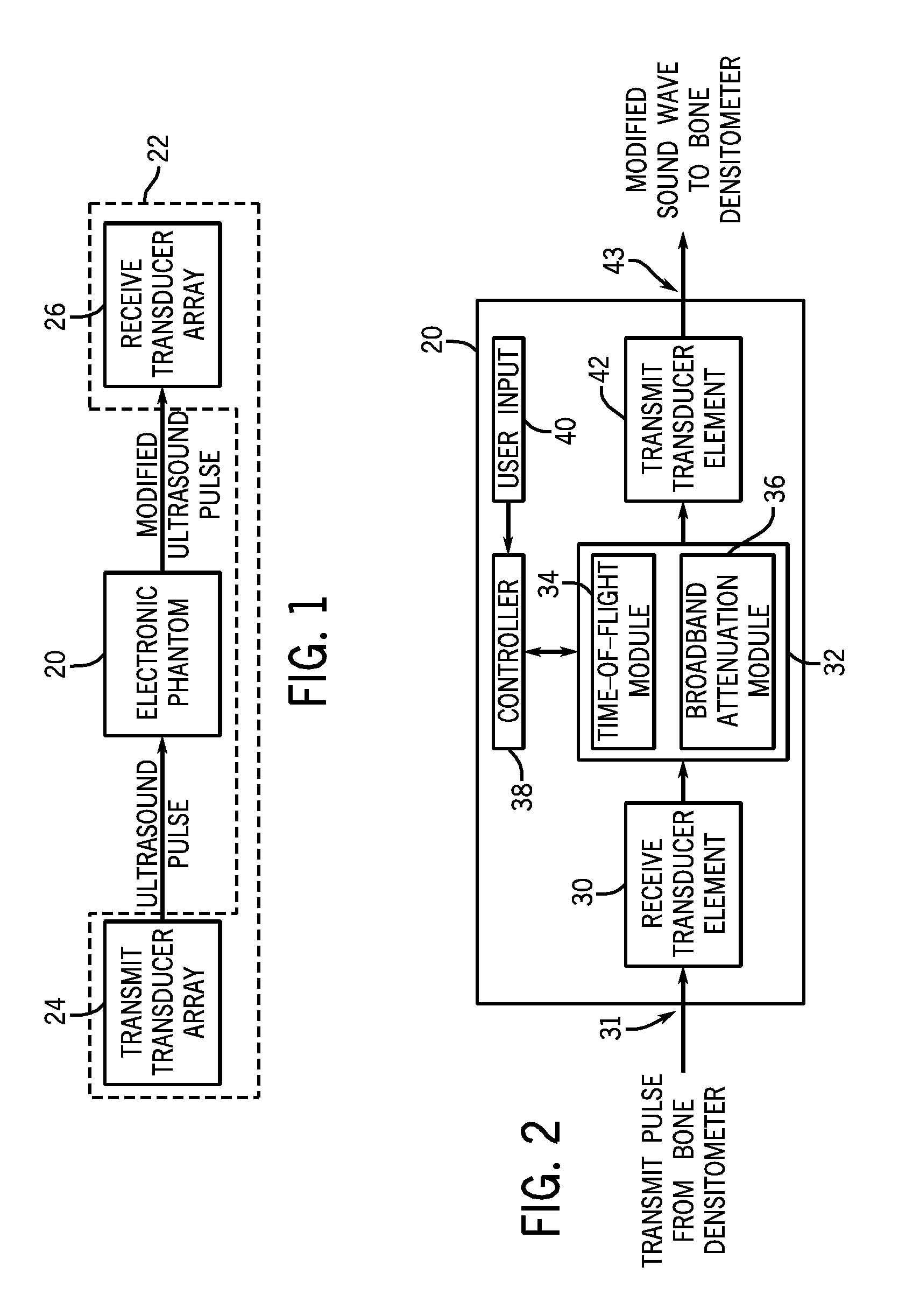
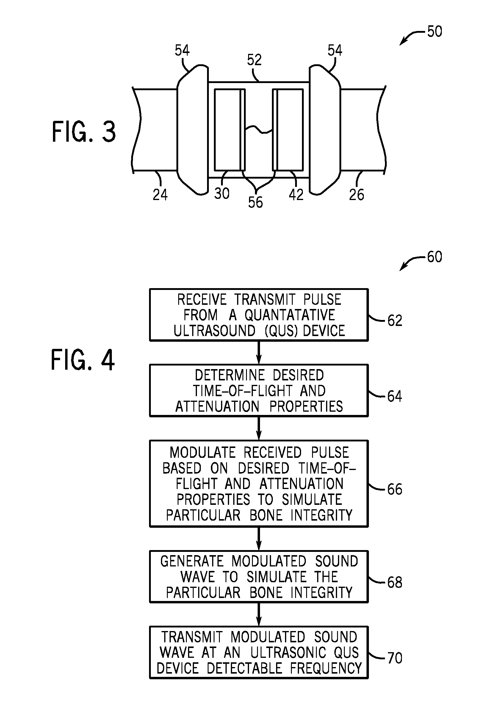
The patent describes an electronic phantom for a quantitative ultrasound device. The phantom includes a housing and two transducer elements within the housing. The second transducer element is connected to the first and is capable of transmitting a modified ultrasonic sound wave to the device based on the received ultrasonic signal. The first and second transducer elements are positioned in a back to back configuration within the housing. The patent also describes a method for electronically mimicking a bone by determining its acoustic properties and modulating the received ultrasonic signal based on these properties to produce a modified ultrasonic signal for testing the device.

Problems solved by technology

Accordingly, the interaction of the acoustic wave from the QUS device and the phantom do not mimic bone, resulting in simulations that may not be particularly accurate.
Additionally, liquids such as water are not very attenuative, such that the QUS device operates at minimum power.
For example, materials with good BUA characteristics are typically rubbery.
This cross-linking results in a harder material and changes in the acoustic properties.
The change in material hardness thereby reduces the utility of the QUS phantom for long term monitoring.

Method used


Image

  • Electronic phantom and method for electronically controlling a phantom for a quantitative ultrasound device
  • Electronic phantom and method for electronically controlling a phantom for a quantitative ultrasound device
  • Electronic phantom and method for electronically controlling a phantom for a quantitative ultrasound device

Examples


Embodiment Construction

[0015]The foregoing summary, as well as the following detailed description of certain embodiments, will be better understood when read in conjunction with the appended drawings. To the extent that the figures illustrate diagrams of the functional blocks of various embodiments, the functional blocks are not necessarily indicative of the division between hardware circuitry. One or more of the functional blocks (e.g., processors or memories) may be implemented in a single piece of hardware (e.g., a general purpose signal processor or random access memory, hard disk, or the like) or multiple pieces of hardware. Similarly, the programs may be stand alone programs, may be incorporated as subroutines in an operating system, may be functions in an installed software package, and the like. It should be understood that the various embodiments are not limited to the arrangements and instrumentality shown in the drawings.

[0016]As used herein, an element or step recited in the singular and proce...


PUM


Abstract

An electronic phantom and method for electronically controlling a phantom for a quantitative ultrasound device are provided. The electronic phantom includes a housing, a first transducer element within the housing configured to receive an ultrasonic signal from a quantitative ultrasound device and a second transducer element within the housing connected to the first transducer element. The second transducer element is configured to transmit a modified ultrasonic sound wave to the quantitative ultrasound device based on the received ultrasonic signal. The first and second transducer elements are positioned in a back to back configuration within the housing.

Description

BACKGROUND OF THE INVENTION[0001]The subject matter disclosed herein relates generally to medical diagnostic systems, and more particularly to quantitative ultrasound (QUS) devices.[0002]QUS devices such as ultrasonic densitometers and ultrasonometers use ultrasonic sound waves to measure bone integrity. Validation of QUS devices is an important function to ensure continued proper measurements that allow for proper diagnosis. QUS devices must remain stable for many years in order to properly assess the advancement of osteoporosis or monitor therapies. Thus, measurement parameters such as speed of sound (SOS), also referred to as time-of-flight, and broadband ultrasonic attenuation (BUA) need to be properly measured over time.[0003]QUS phantoms are used to monitor QUS device stability. Conventional QUS phantoms use stable and well-characterized liquids such as water to attenuate signals. Other conventional QUS phantoms use a solid material such as rubber with known ultrasonic propert...

Claims


Application Information

Patent Timeline
Patent Type & Authority Patents(United States)
IPC IPC(8): G09B23/28
CPCA61B8/0875A61B8/587G09B23/286
Inventor MORRIS, RICHARD FRANKLINMORRIS, STEVEN TAYLOR
Owner GENERAL ELECTRIC CO
Learn More