
System and method for multi-image based stent visibility enhancement

a multi-image, stent technology, applied in image enhancement, image analysis, instruments, etc., can solve the problems of low signal-to-noise ratio of images, over-simplification of previous assumptions, and only providing traditional averaging, so as to enhance the visibility of stents in digital medical images

Inactive Publication Date: 2013-04-30
SIEMENS HEALTHCARE GMBH
View PDF2 Cites 40 Cited by
  • Summary
  • Abstract
  • Description
  • Claims
  • Application Information

AI Technical Summary

Benefits of technology

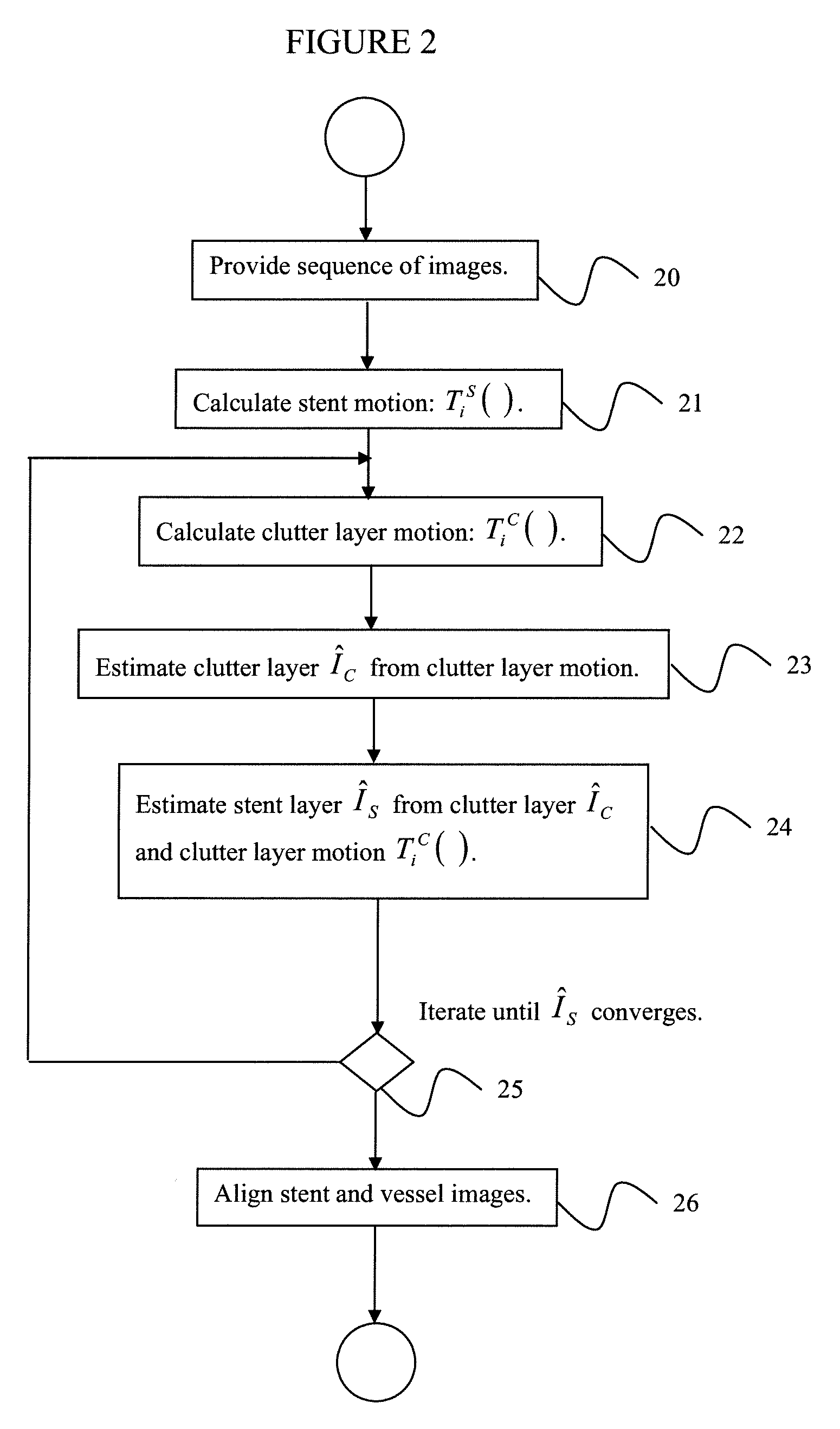
[0009]According to an aspect of the invention, there is provided a method for enhancing stent visibility in digital medical images, including providing a time series of 2-dimensional (2D) images of a stent in a vessel, estimating motion of the stent in a subset of images of the time series of images, estimating motion of clutter in the subset of images, where clutter comprises anatomical structures other than the stent, estimating a clutter layer in the subset of images from the estimated clutter motion, estimating a stent layer in the subset of images from the clutter layer and the estimated clutter motion, and minimizing a functional of the estimated stent motion, the estimated stent layer, the estimated clutter motion, and the estimated clutter layer to calculate a refined stent layer image, where the refined stent layer image has enhanced visibility of the stent.
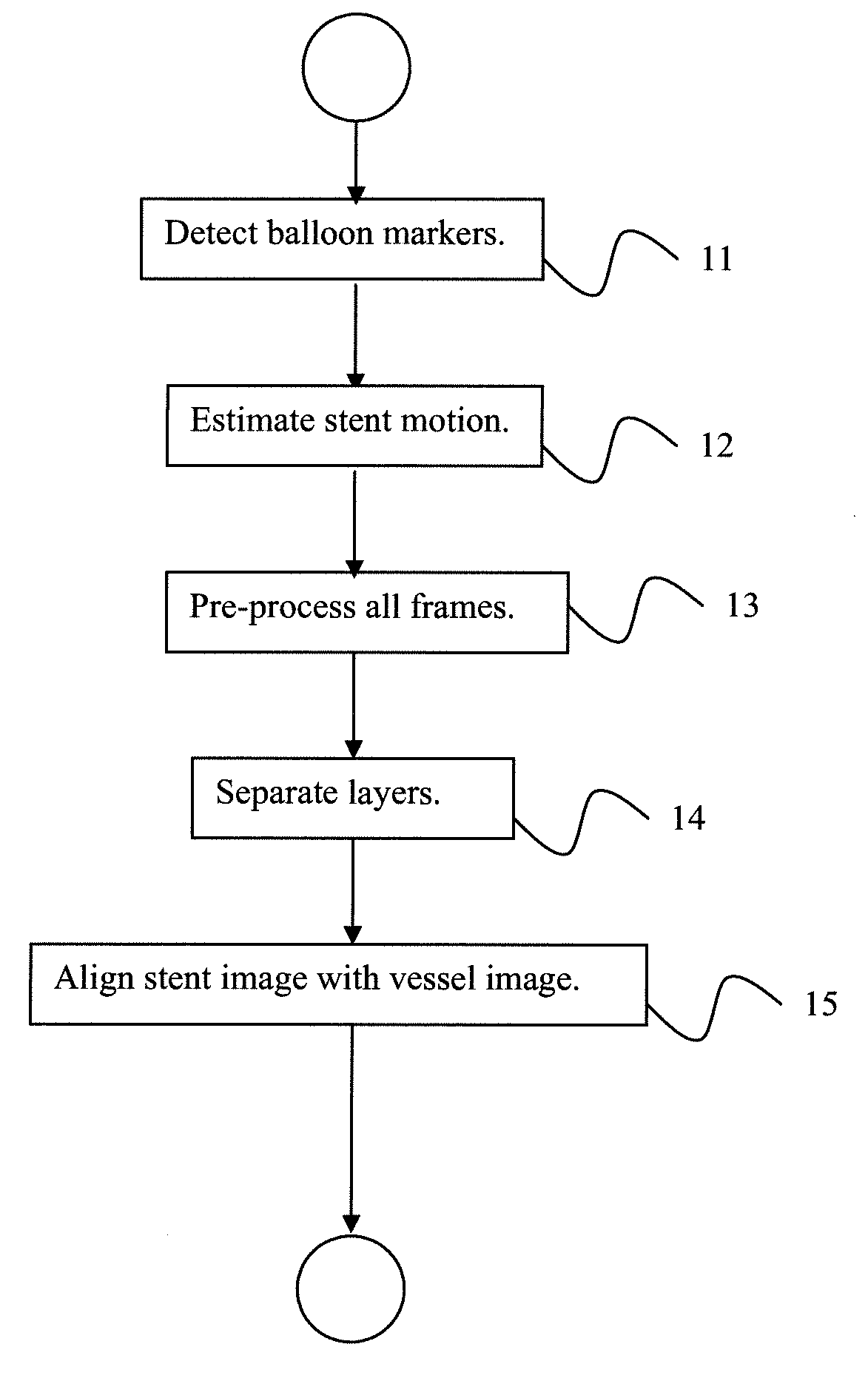
[0023]According to a another aspect of the invention, there is provided a method for enhancing stent visibility in digital medical images, including providing a time series of 2-dimensional (2D) images of a stent in a vessel, where the stent has a pair of balloon markers attached thereto, attempting to detect a 2D location of the balloon markers in each of the images, and selecting a subset of images having as members those images in which the balloon marker locations are detectable, estimating motion of the stent from the 2D balloon marker locations in each image of the subset of images, pre-processing each image in the subset of images to make the image intensities additive, and to compensate for changes in lighting in the images of the subset of images, separating an image layer containing the stent from an image layer containing clutter in each image of the subset of images, where clutter comprises anatomical structures other than the stent, and aligning the stent image layer with an image of the vessel, where the aligned images have enhanced visibility of the stent placement in the vessel.
[0024]According to a further aspect of the invention, separating an image layer containing the stent from an image layer containing clutter in each image includes estimating clutter motion in the subset of images, estimating a clutter layer in the subset of images from the estimated clutter motion, estimating a stent layer in the subset of images from the clutter layer and the estimated clutter motion, and repeating the steps of estimating clutter motion, estimating a clutter layer, and estimating a stent layer until the refined stent layer image converges, where the refined stent layer image has enhanced visibility of the stent.
[0027]According to a another aspect of the invention, there is provided a program storage device readable by a computer, tangibly embodying a program of instructions executable by the computer to perform the method steps for enhancing stent visibility in digital medical images.

Problems solved by technology

However, the image's signal to noise ratio is usually very low due to the low-dosage imaging conditions prevalent during the intervention procedures.
However, the previous assumption is over-simplified because the images also include other patient organs and vessels which do not belong to the stent image.
Traditional averaging can only provide a result that s a mixture of the true stent image and a motion blurred clutter layer.

Method used


Image

  • System and method for multi-image based stent visibility enhancement
  • System and method for multi-image based stent visibility enhancement
  • System and method for multi-image based stent visibility enhancement

Examples


Embodiment Construction

[0032]Exemplary embodiments of the invention as described herein generally include systems and methods for to enhancing the visibility of stents in digital medical images. Accordingly, while the invention is susceptible to various modifications and alternative forms, specific embodiments thereof are shown by way of example in the drawings and will herein be described in detail. It should be understood, however, that there is no intent to limit the invention to the particular forms disclosed, but on the contrary, the invention is to cover all modifications, equivalents, and alternatives falling within the spirit and scope of the invention.

[0033]As used herein, the term “image” refers to multi-dimensional data composed of discrete image elements (e.g., pixels for 2-D images and voxels for 3-D images). The image may be, for example, a medical image of a subject collected by computer tomography, magnetic resonance imaging, ultrasound, or any other medical imaging system known to one of ...


PUM


Abstract

A method for enhancing stent visibility in digital medical images includes providing a time series of 2-dimensional (2D) images of a stent in a vessel, estimating motion of the stent in a subset of images of the time series of images, estimating motion of clutter in the subset of images, where clutter comprises anatomical structures other than the stent, estimating a clutter layer in the subset of images from the estimated clutter motion, estimating a stent layer in the subset of images from the clutter layer and the estimated clutter motion, and minimizing a functional of the estimated stent motion, the estimated stent layer, the estimated clutter motion, and the estimated clutter layer to in calculate a refined stent layer image, where the refined stent layer image has enhanced visibility of the stent.

Description

CROSS REFERENCE TO RELATED UNITED STATES APPLICATIONS[0001]This application claims priority from “Multi-image Based Stent Visibility Enhancement”, U.S. Provisional Application No. 61 / 243,266 of Chen, et al., filed Sep. 17, 2009, the contents of which are herein incorporated by reference in their entirety.TECHNICAL FIELD[0002]This disclosure is directed to enhancing the visibility of stents in digital medical mages.DISCUSSION OF THE RELATED ART[0003]During a stent placement procedure, a sequence of fluoroscopic X-ray images is usually acquired to check the stent position. Thus, stent visibility in a fluoroscopic image is of great importance in an intervention procedure for accurate stent placement. However, the image's signal to noise ratio is usually very low due to the low-dosage imaging conditions prevalent during the intervention procedures.[0004]Images are typically modeled as additive signal. For X-Ray images, this can be satisfied by applying a log function to image intensity....

Claims


Application Information

Patent Timeline
Patent Type & Authority Patents(United States)
IPC IPC(8): G06K9/00
CPCG06K9/6206G06T5/001G06T5/20G06T5/50G06K2209/057G06T2207/10121G06T2207/30101G06T2207/10016G06V10/754G06V2201/034G06T5/003
Inventor CHEN, YUNQIANGCHANG, TI-CHIUNYAN, MICHELLE XIAOHONGFANG, TONGPOHL, THOMASBOHM, STEFANDURLAK, PETERRO.BETA.MEIER, MARKUS
Owner SIEMENS HEALTHCARE GMBH
Learn More