Wind turbine having a high-voltage ride through (HVRT) mode

a high-voltage ride-through, wind turbine technology, applied in the direction of motor/generator/converter stopper, electric generator control, dynamo-electric converter control, etc., can solve the problem of supplying a relatively high breakdown voltage, damage to the dc link capacitor, and a relatively large and bulky dc bus capacitor

Inactive Publication Date: 2013-04-30
GENERAL ELECTRIC CO
View PDF12 Cites 16 Cited by
  • Summary
  • Abstract
  • Description
  • Claims
  • Application Information

AI Technical Summary

Problems solved by technology

However, an over-voltage condition in the power grid may cause issues with the operation of the power converter.
Specifically, for example, if the voltage to a DC link capacitor is above a breakdown voltage of the DC link capacitor, this may damage the DC link capacitor.
Thus, a relatively large and bulky DC bus capacitor having a relatively high breakdown voltage may be provided.
However, providing large, bulky capacitors and inductors adds cost and complexity to the wind turbine.

Method used


Image

  • Wind turbine having a high-voltage ride through (HVRT) mode
  • Wind turbine having a high-voltage ride through (HVRT) mode
  • Wind turbine having a high-voltage ride through (HVRT) mode

Examples


Embodiment Construction

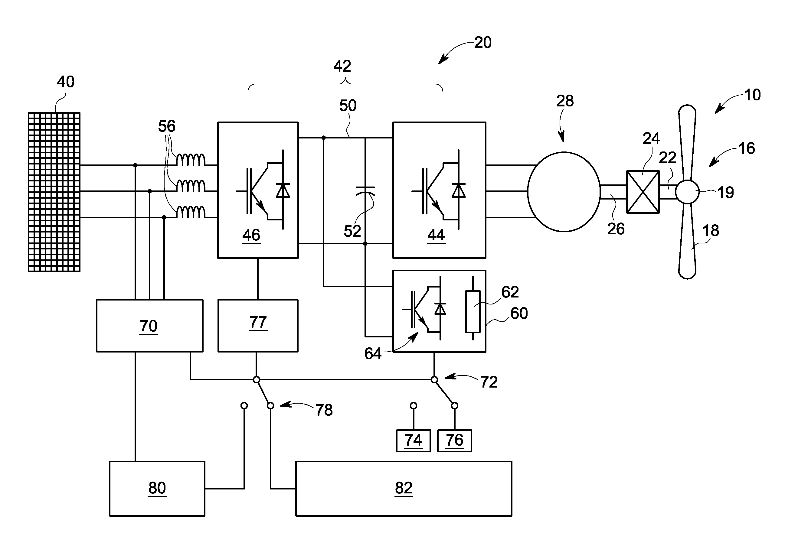
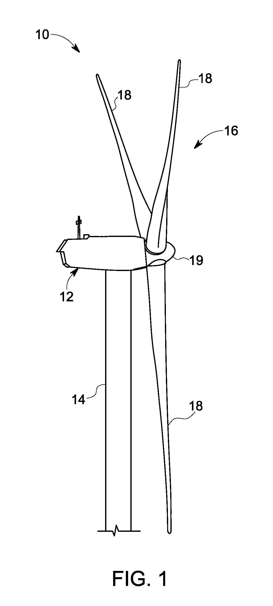
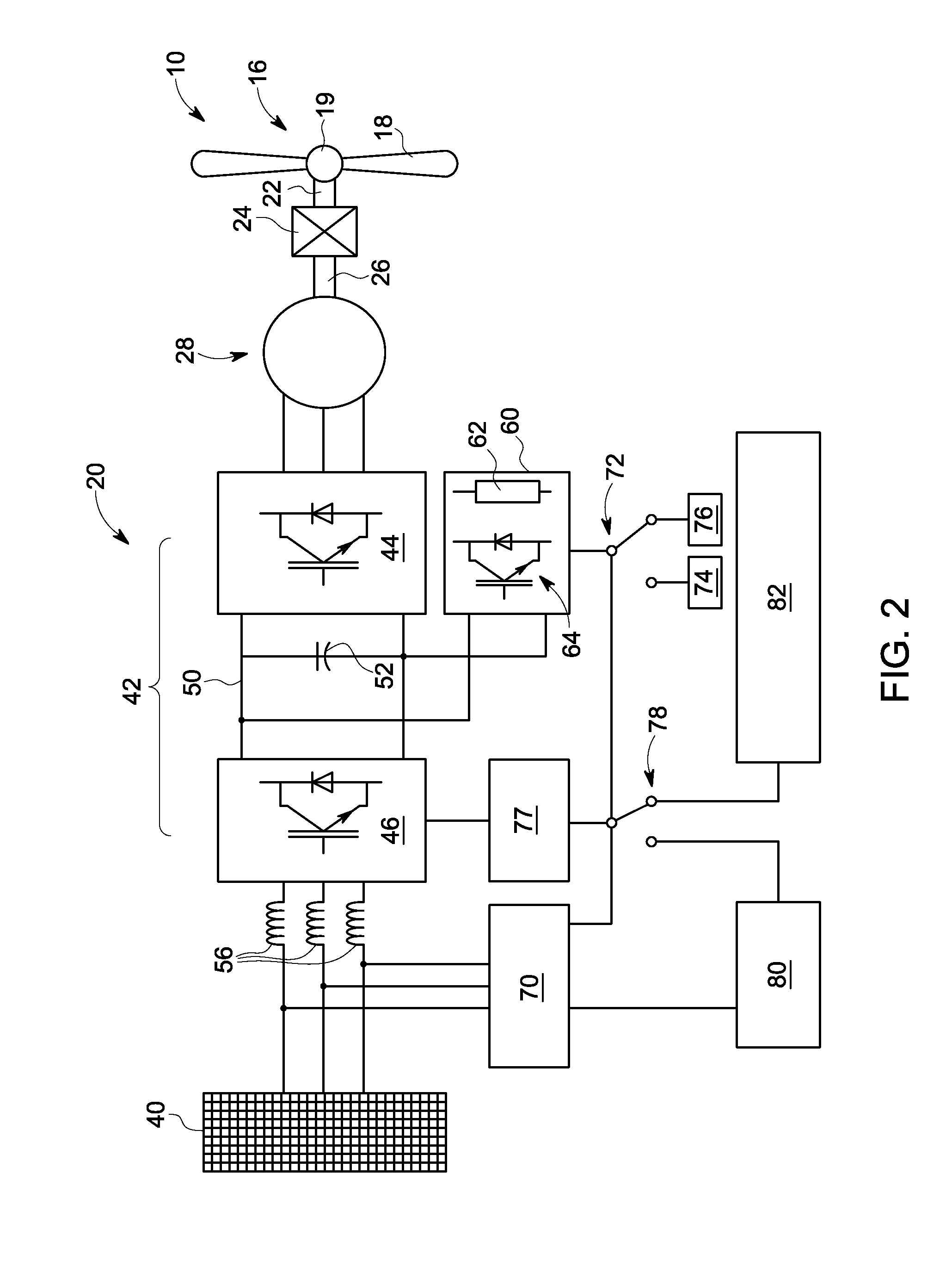
[0014]As used herein, the term “blade” is intended to be representative of any device that provides a reactive force when in motion relative to a surrounding fluid. As used herein, the term “wind turbine” is intended to be representative of any device that generates rotational energy from wind energy, and more specifically, converts kinetic energy of wind into mechanical energy. The term “control module” refers to an application specific integrated circuit (ASIC), an electronic circuit, a processor (shared, dedicated, or group) and memory that executes one or more software or firmware programs, a combinational logic circuit, and / or other suitable components that provide the described functionality. As used herein, the term “brake chopper” is intended to be representative of any device that includes a switch that connects a DC bus voltage to a resistive element, where the resistive element converts electrical energy to heat.

[0015]FIG. 1 is a perspective view of a portion of an exempl...


PUM


Abstract

A wind turbine connected to a power grid is provided. The wind turbine is selectively activated to operate at a high-voltage ride through (HVRT) mode. The wind turbine includes a grid voltage circuit, a DC bus, a voltage source, and a dynamic brake. The grid voltage circuit monitors a fundamental voltage of the power grid and activates the HVRT mode if the fundamental voltage is at least about equal to a threshold voltage value. The DC bus has a DC bus voltage. The voltage source provides a DC bus rated voltage. The dynamic brake has a brake chopper and a resistive element. The dynamic brake is connected to the DC bus. The dynamic brake is connected to the voltage source if the HVRT mode is activated.

Description

BACKGROUND OF THE INVENTION[0001]The subject matter disclosed herein relates to a wind turbine, and more specifically to a wind turbine having a high-voltage ride through (HVRT) mode.[0002]Generally, a wind turbine includes a turbine that has a rotor that includes a rotatable hub assembly having multiple blades. The blades transform wind energy into a mechanical rotational torque that drives one or more generators via the rotor. The generators are sometimes, but not always, rotationally coupled to the rotor through a gearbox. The gearbox steps up the inherently low rotational speed of the rotor for the generator to efficiently convert the rotational mechanical energy to electrical energy, which is fed into a utility grid via at least one electrical connection. Gearless direct drive wind turbines also exist. The rotor, generator, gearbox and other components are typically mounted within a housing, or nacelle, that is positioned on top of a base that may be a truss or tubular tower.[0...

Claims


Application Information

Patent Timeline
Patent Type & Authority Patents(United States)
IPC IPC(8): F03D9/00H02P11/00
CPCF03D9/003H02P3/18H02J3/14H02P9/006Y02E10/72F03D9/255H02J2310/58
Inventor GRBOVIC, PETAR JOVAN
Owner GENERAL ELECTRIC CO
Why Eureka
Try Eureka