Drive device for linear body
a technology of driving device and linear body, which is applied in the direction of catheters, intravenous devices, occulders, etc., can solve the problems of delicate control of catheter treatment, and achieve the effect of facilitating resumption of surgery
- Summary
- Abstract
- Description
- Claims
- Application Information
AI Technical Summary
Benefits of technology
Problems solved by technology
Method used
Image
Examples
first embodiment
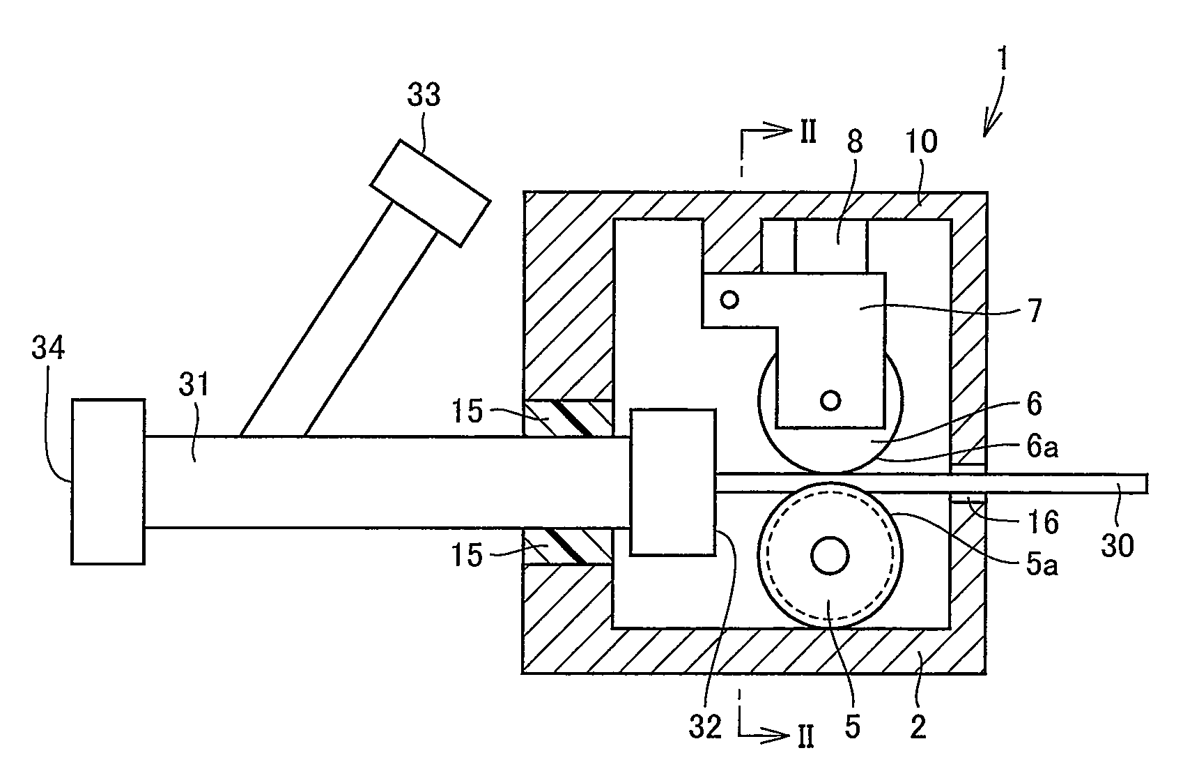
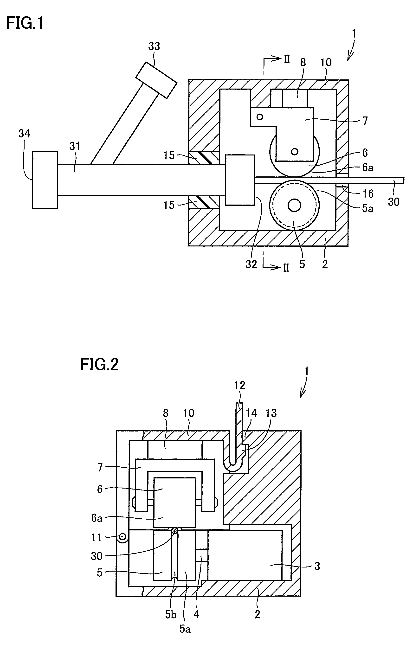
[0028]FIG. 1 is a schematic cross section of a drive device for a linear body in a first embodiment. FIG. 2 is a partial schematic cross section of the drive device for the linear body, taken along a line II-II shown in FIG. 1. As shown in FIG. 1 and FIG. 2, a drive device 1 includes a housing 2. Housing 2 has a lid member 10 opened and closed, as desired, as it pivots around a hinge 11 serving as a spindle.
[0029]Housing 2 and lid member 10 define an internal space of drive device 1. In the internal space, a motor 3 serving as a torque generator, a rotary shaft 4 transmitting the torque generated by motor 3, and a driving roller 5 providing a rotational motion by the torque transmitted via rotary shaft 4 are provided. Driving roller 5, which is attached to motor 3 and serves as a feed roller, is generally cylindrical. Driving roller 5 has a cylindrical side surface, or a rotation surface 5a, having a feed groove 5b.
[0030]Disposed opposite to the driving roller 5 rotation surface 5a...
second embodiment
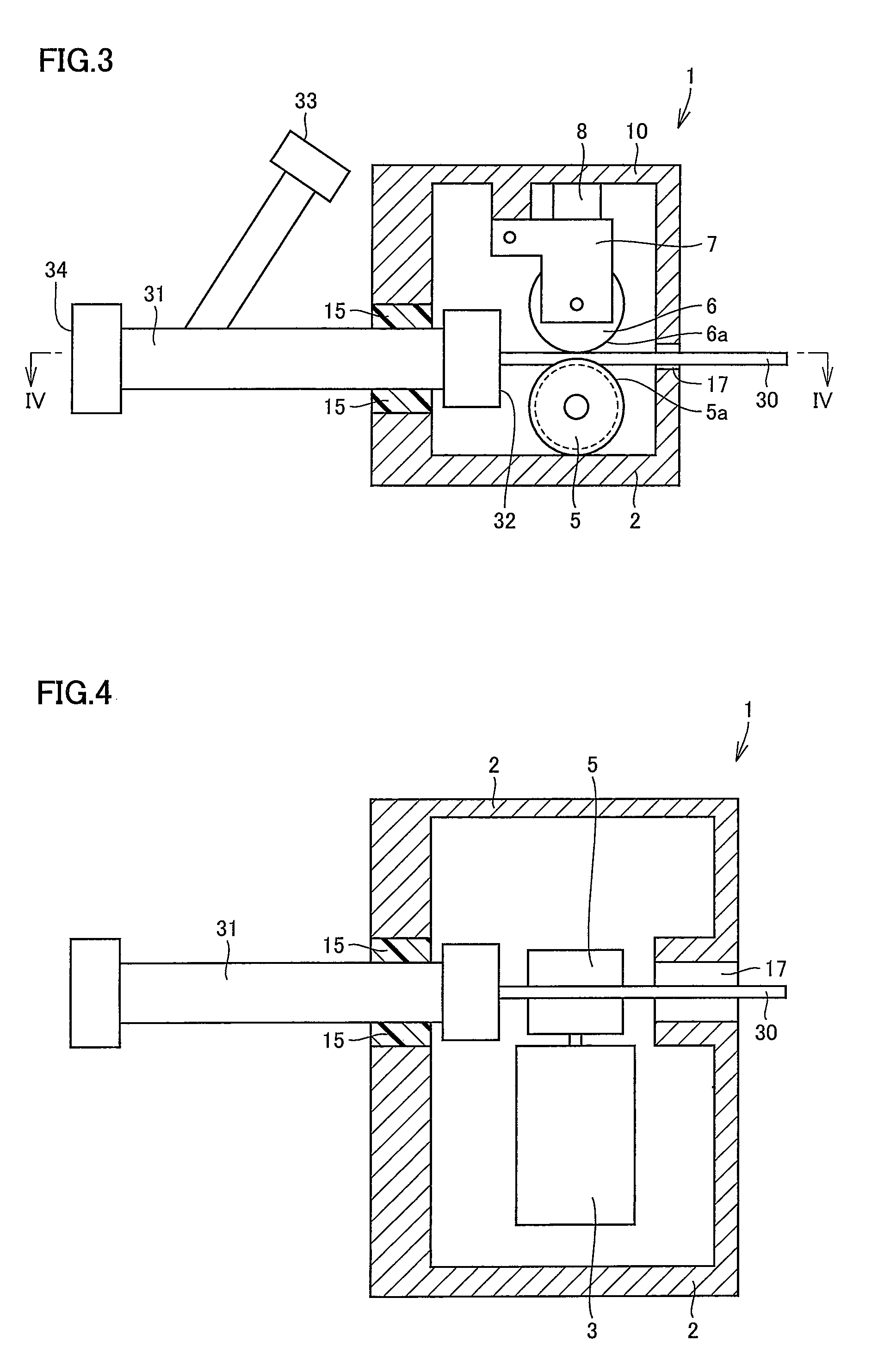
[0048]FIG. 3 is a schematic cross section of a drive device for a linear body in a second embodiment, taken along a line shown in FIG. 5. FIG. 4 is a partial schematic cross section of the drive device for the linear body, taken along a line Iv-Iv shown in FIG. 3. FIG. 5 is a side view of the drive device for the linear body in the second embodiment. The second embodiment provides drive device 1 for linear body 30, that is different from the first embodiment in that the former has housing 2 and lid member 10 aligned at a portion shaped as shown in FIG. 3 to FIG. 5.
[0049]More specifically, elastic portion 15 is provided at one sidewall, and at the other sidewall opposite thereto, housing 2 has a portion aligned with lid member 10 and having a guide groove 17. Lid member 10 at the other sidewall has a raised portion 18 shaped to be fitted into guide groove 17. When lid member 10 is closed, raised portion 18 is fitted into guide groove 17, and raised portion 18 and guide groove 17 toge...
PUM
 Abstract
Description
Claims
Application Information
 - R&D
- Intellectual Property
- Life Sciences
- Materials
- Tech Scout
- Unparalleled Data Quality
- Higher Quality Content
- 60% Fewer Hallucinations
Browse by: Latest US Patents, China's latest patents, Technical Efficacy Thesaurus, Application Domain, Technology Topic, Popular Technical Reports.
© 2025 PatSnap. All rights reserved.Legal|Privacy policy|Modern Slavery Act Transparency Statement|Sitemap|About US| Contact US: help@patsnap.com


