Charger and a combination structure
a combination structure and charger technology, applied in the direction of hinges, manufacturing tools, coupling device connections, etc., can solve the problems of inconvenience in use, user may not find a charger, and the conventional socket is not provided with a charger, so as to achieve the effect of convenient charging
- Summary
- Abstract
- Description
- Claims
- Application Information
AI Technical Summary
Benefits of technology
Problems solved by technology
Method used
Image
Examples
first embodiment
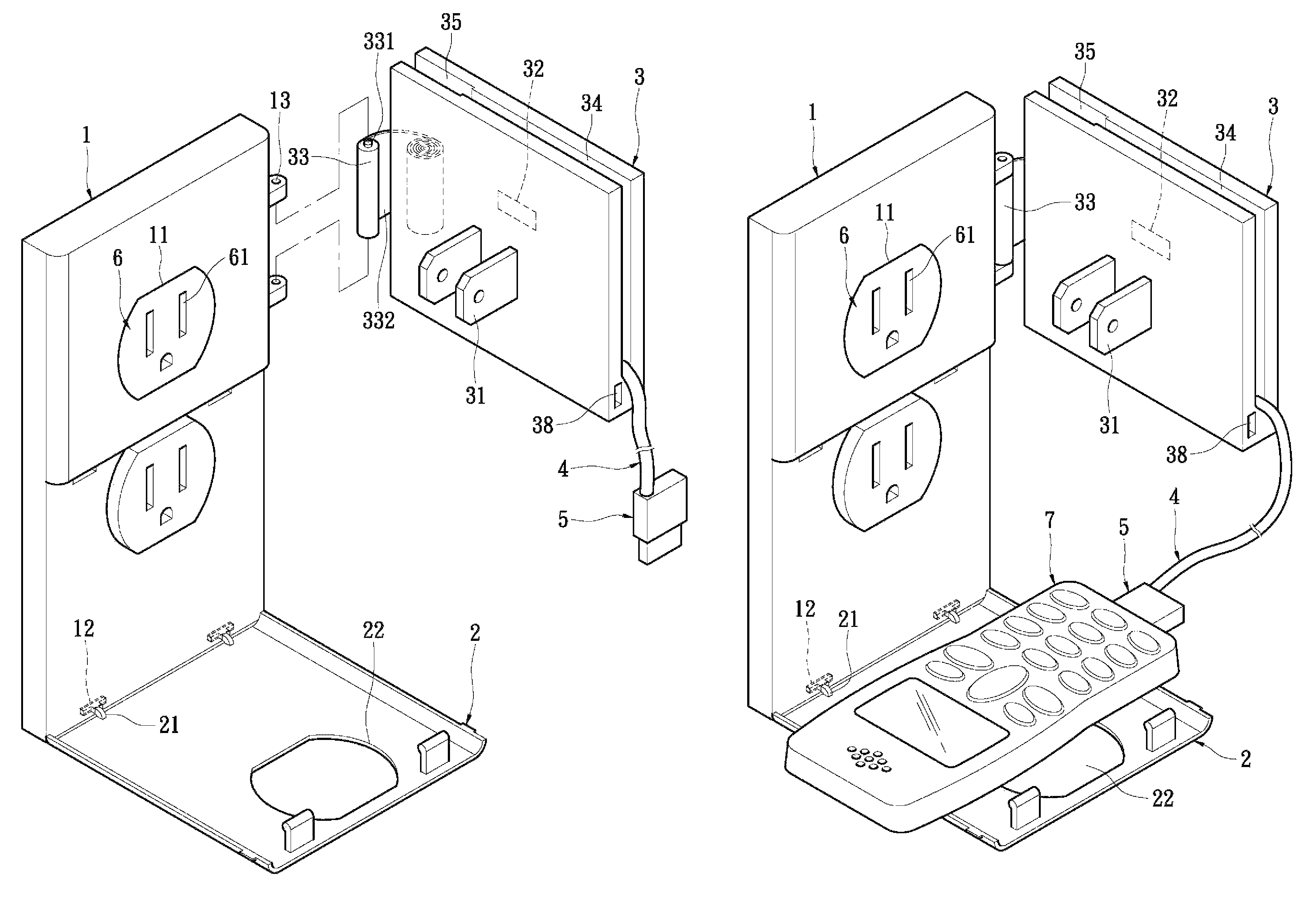
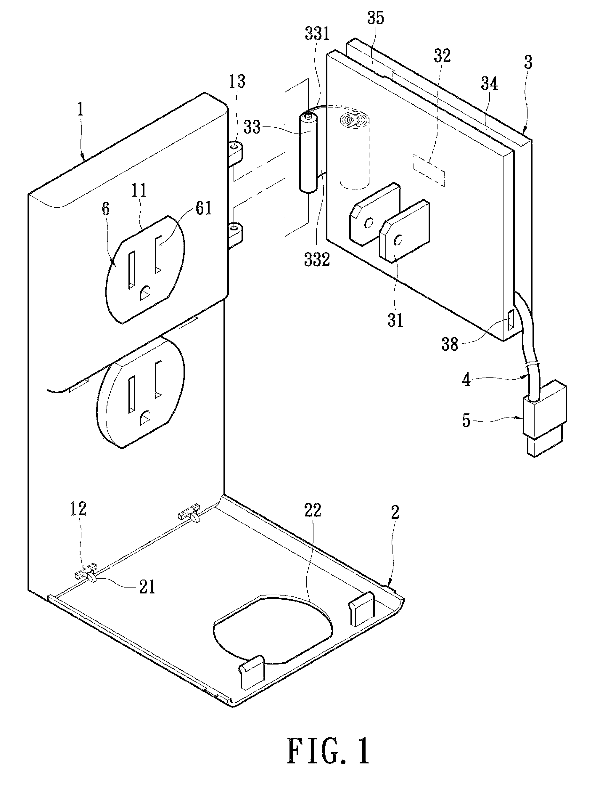
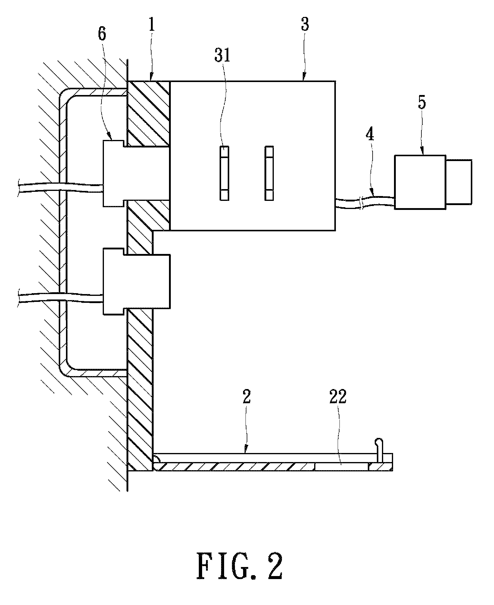
[0029]Please refer to FIGS. 1 to 3, which show the combination structure according to the present invention. The combination structure adapted to house a socket unit includes a socket panel 1, a supporting plate 2, a charger 3, a connecting line 4, and an electrical connector 5. The socket panel 1 is a square plate. However, the shape and dimensions of the socket panel 1 are not limited thereto and can be varied suitably based on practical demands. The socket panel 1 can be constituted of single or multiple layers of plates. The socket plate 1 configured to exposingly house the socket unit 6 is provided with at least one engaging portion 11. The engaging portion 11 is a through-hole corresponding to the socket unit 6, so that the engaging portion 11 can be engaged with the outer edge of the socket unit 6. The bottom side of the socket panel 1 is provided with two juxtaposed first pivoting portions 12. The two first pivoting portions 12 are pivot holes. In the present embodiment, the...
second embodiment
[0038]Please refer to FIG. 5. In the present invention, the panel connecting piece 33 has a leaf spring 332 that can be wound or unwound elastically. One end of the leaf spring 332 is fixed to the charger 3, and the other end of the leaf spring 332 is formed with a shaft 333. One side of the socket panel 1 is provided with a connecting hole 14. The shaft 333 is pivoted to the connecting hole 14, thereby forming a pivot structure. Via this arrangement, the charger 3 can be pivoted to and flipped over one side of the socket panel 1. Thus, the charger 3 can be extended outwards via the leaf spring. The shaft 333 and the connecting hole 14 can be detached; therefore the charger 3 can be separated from the socket panel 1 so that the charger 3 may be taken away separately. The leaf spring 332 can be provided with graduations 334, so that the charger 3 can be used as a tape measure after being detached from the socket panel 1. The terminals 31 can be folded. In the present embodiment, the ...
third embodiment
[0039]Please refer to FIG. 6. In the present invention, the shapes of the socket panel 1 and the charger 3 are varied. Further, the socket unit 6 conforms to the European standard.
PUM
 Abstract
Description
Claims
Application Information
 - R&D
- Intellectual Property
- Life Sciences
- Materials
- Tech Scout
- Unparalleled Data Quality
- Higher Quality Content
- 60% Fewer Hallucinations
Browse by: Latest US Patents, China's latest patents, Technical Efficacy Thesaurus, Application Domain, Technology Topic, Popular Technical Reports.
© 2025 PatSnap. All rights reserved.Legal|Privacy policy|Modern Slavery Act Transparency Statement|Sitemap|About US| Contact US: help@patsnap.com


