Eureka AIR delivers breakthrough ideas for toughest innovation challenges, trusted by R&D personnel around the world.

Insertion devices for infusion devices

a technology for insertion devices and infusion devices, which is applied in the direction of intravenous devices, infusion needles, other medical devices, etc., can solve the problems of difficult fine motor control, insufficient insertion devices, and complicated insertion, so as to minimize the possibility of accidental needle sticks and/or insertion, easy grasping and operation, and fine motor control

Active Publication Date: 2013-04-02
YPSOMED AG
View PDF148 Cites 110 Cited by
  • Summary
  • Abstract
  • Description
  • Claims
  • Application Information

AI Technical Summary

Benefits of technology

[0008]Prior insertion devices do not adequately address the needs of users. Some users may suffer from conditions, such as diabetic neuropathy. It can be advantageous for an insertion device for an infusion device to be easily grasped and operated by diabetics suffering from diabetic neuropathy. Diabetic neuropathy can cause numbness, loss of feeling and muscle weakness in the hands and fingers making fine motor control difficult. At times, a user may need to insert an infusion device at a location on the user's body which may complicate insertion, e.g., on a user's side or back. In some instances, an adult may need to assist a child in placing an infusion device on the child's body. In these instances and others, it can be beneficial for an insertion device for an infusion device to require a minimum number of operational steps while providing safe operation and disposal. Such an insertion device may advantageously minimize the possibility of accidental needle sticks and / or premature activation of the insertion device. Accordingly, it can be advantageous for an insertion device to insert an infusion device, such as an infusion set, quickly, safely, and conveniently.
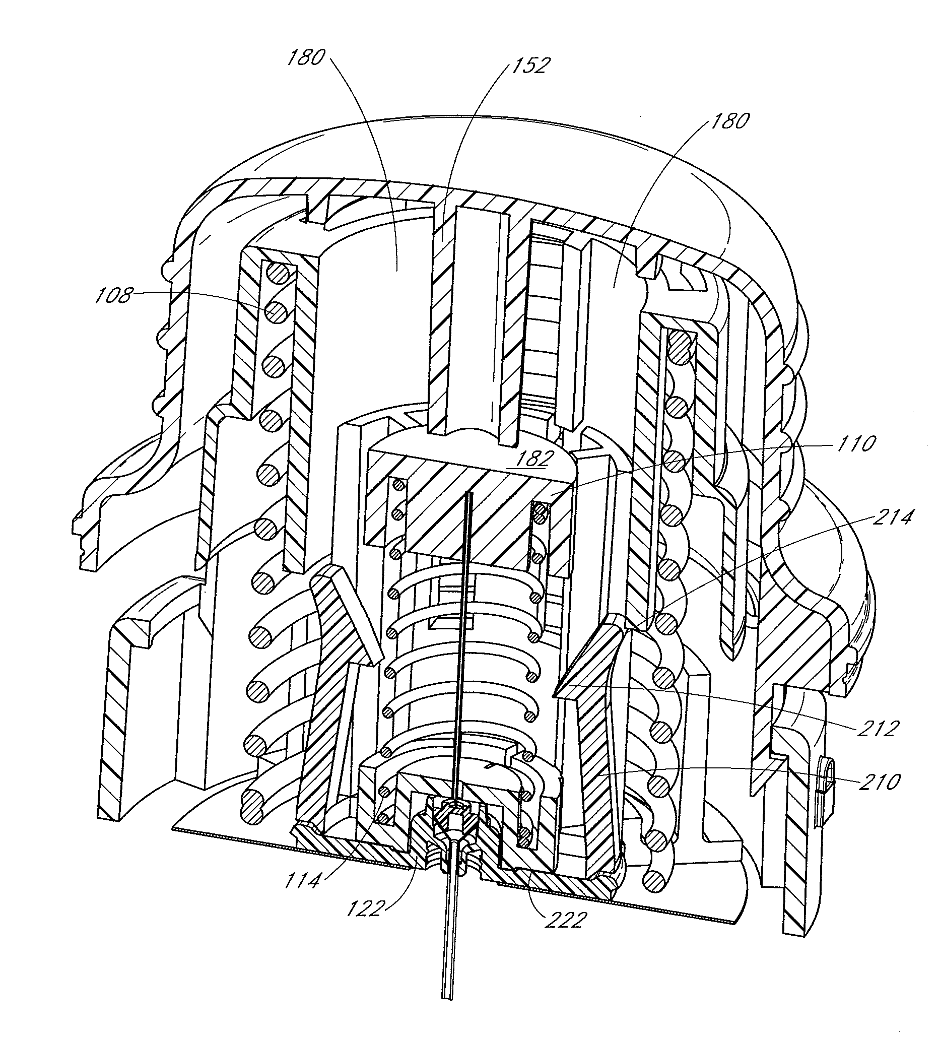
[0012]The hub can have an upper side and a lower side. The hub can be movable between a first position and a second position with respect to the shuttle. The first hub-retaining arm of the shuttle can inhibit movement of the hub away from the shuttle when the hub is in the first position.
[0014]The actuator can be movably attached to the sleeve such that, when the first movement-restraining arm is engaged with the upper surface, advancement of the actuator toward the sleeve permits disengagement the first movement-restraining arm of the shuttle from the upper surface of the sleeve. Disengagement of the first movement-restraining arm of the shuttle from the upper surface of the sleeve can allow the first biasing member to move the shuttle from the retracted position to the advanced position. Movement of the shuttle from the retracted position to the advanced position can allow the first hub-retaining arm of the shuttle to release the hub such that the second biasing member moves the hub from the first position to the second position.
[0019]The actuator can be operatively connected to the sleeve to cause the first biasing member to move the carriage from the retracted position to the advanced position. Movement of the carriage from the retracted position toward the advanced position permits the hub to move from the first position to the second position.

Problems solved by technology

Prior insertion devices do not adequately address the needs of users.
Diabetic neuropathy can cause numbness, loss of feeling and muscle weakness in the hands and fingers making fine motor control difficult.
At times, a user may need to insert an infusion device at a location on the user's body which may complicate insertion, e.g., on a user's side or back.

Method used


Image

  • Insertion devices for infusion devices
  • Insertion devices for infusion devices
  • Insertion devices for infusion devices

Examples


Embodiment Construction

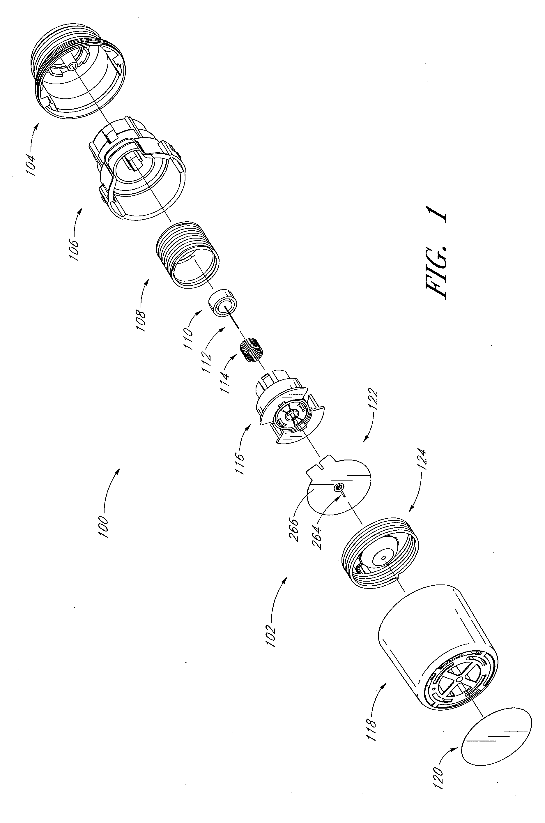
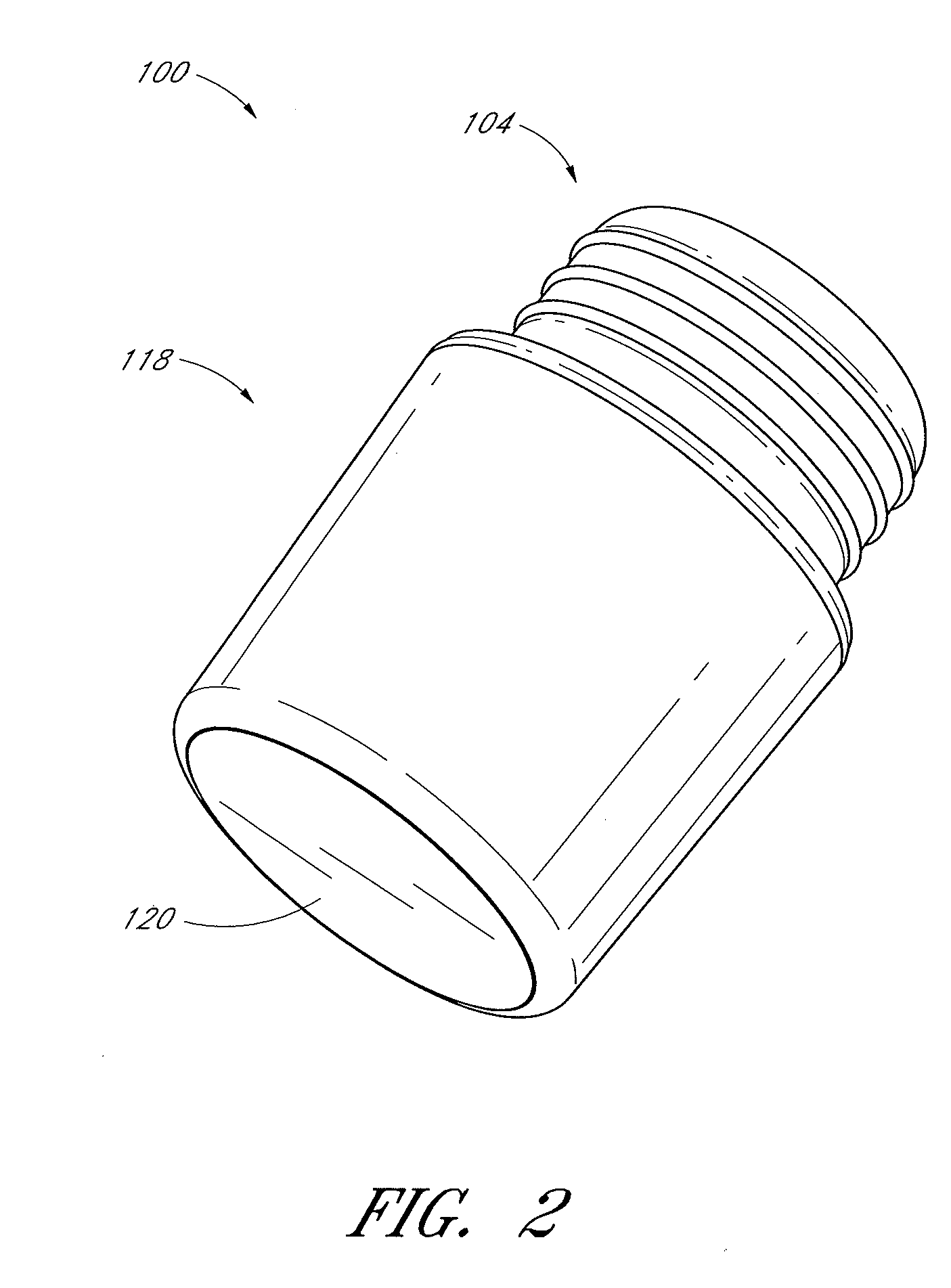
[0057]FIG. 1 illustrates an embodiment of an insertion device 100 for an infusion device 102, such as infusion set. Further details regarding some exemplifying infusion devices, including infusion sets, are provided in United States Patent Application Publication Nos. 2005 / 0107743 and 2007 / 0185441, both of which are hereby incorporated by reference herein in their entireties. There are many different types of infusion devices, such as infusion sets, that may be inserted using insertion devices, and the foregoing publications are provided merely to illustrate some infusion devices that can be used with or adapted to be used with the insertion devices described herein.

[0058]Referring to FIG. 1, the insertion device 100 can comprise an actuator 104, a sleeve 106, an insertion spring 108, a needle hub 110, a needle 112, a retraction spring 114, a shuttle or carriage 116, a protective cap 118, and a cover 120. The infusion device 102 can be an infusion set, and can comprise a base 122 an...


PUM


Abstract

An insertion device for inserting an infusion device at least partially into skin for subcutaneous infusion can comprise a sleeve having a lower surface that is configured to engage the skin, a shuttle or carriage to carry the infusion device between a retracted position and an advanced position; at least a first biasing member to urge the shuttle or carriage toward the advanced position, and an actuator to cause the first biasing member to urge the carriage from the retracted position to the advanced position. In some embodiments, the insertion device can further comprise a hub and at least a second biasing member to urge the hub away from the shuttle or carriage. In some embodiments, the insertion device can further comprise a needle attached to the hub. Methods for inserting an infusion device and various other features that can be comprised by an insertion device are also disclosed.

Description

RELATED APPLICATIONS[0001]This application claims the benefit under 35 U.S.C. §119(e) of U.S. Provisional Application No. 60 / 973,134, filed Sep. 17, 2007, titled INSERTION DEVICE FOR AN INFUSION SET, and U.S. Provisional Application No. 61 / 042,232, filed Apr. 3, 2008, titled INSERTION DEVICE FOR AN INFUSION SET. The entire contents of each of these applications are hereby incorporated by reference herein and made a part of this specification.BACKGROUND[0002]1. Field[0003]The present disclosure relates to devices that facilitate insertion of infusion devices, such as infusion sets, into a subject, and more particularly devices for inserting infusion devices at least partially into a person's skin.[0004]2. Description of the Related Art[0005]Subcutaneous injection is a standard method for the delivery of medication into a patient's body. To facilitate frequent or continuous subcutaneous injection of medication, subcutaneous injection ports are often used. Such injection ports include ...

Claims


Application Information

Patent Timeline
Patent Type & Authority Patents(United States)
IPC IPC(8): A61M5/178
CPCA61M5/14244A61M5/158A61M2005/14252A61M2005/1585A61M2005/1587
Inventor RAYMOND, RANDY STEPHENWALKER, JOSEPH K.LOPEZ, DANWARREN, DEE E.
Owner YPSOMED AG
Why Eureka
Eureka Blog
Learn More