
Universal electric box mounting device

a technology for mounting devices and electric boxes, applied in the direction of electrical apparatus casings/cabinets/drawers, coupling device connections, installation of lighting conductors, etc., can solve the problems of electric boxes, heavy and time-consuming efforts, and become partially or completely dislodged from brackets, so as to prevent slippage or disengagement of electric boxes, the effect of easy maneuverability

Active Publication Date: 2013-03-26
RINDERER ERIC R
View PDF22 Cites 71 Cited by
  • Summary
  • Abstract
  • Description
  • Claims
  • Application Information

AI Technical Summary

Benefits of technology

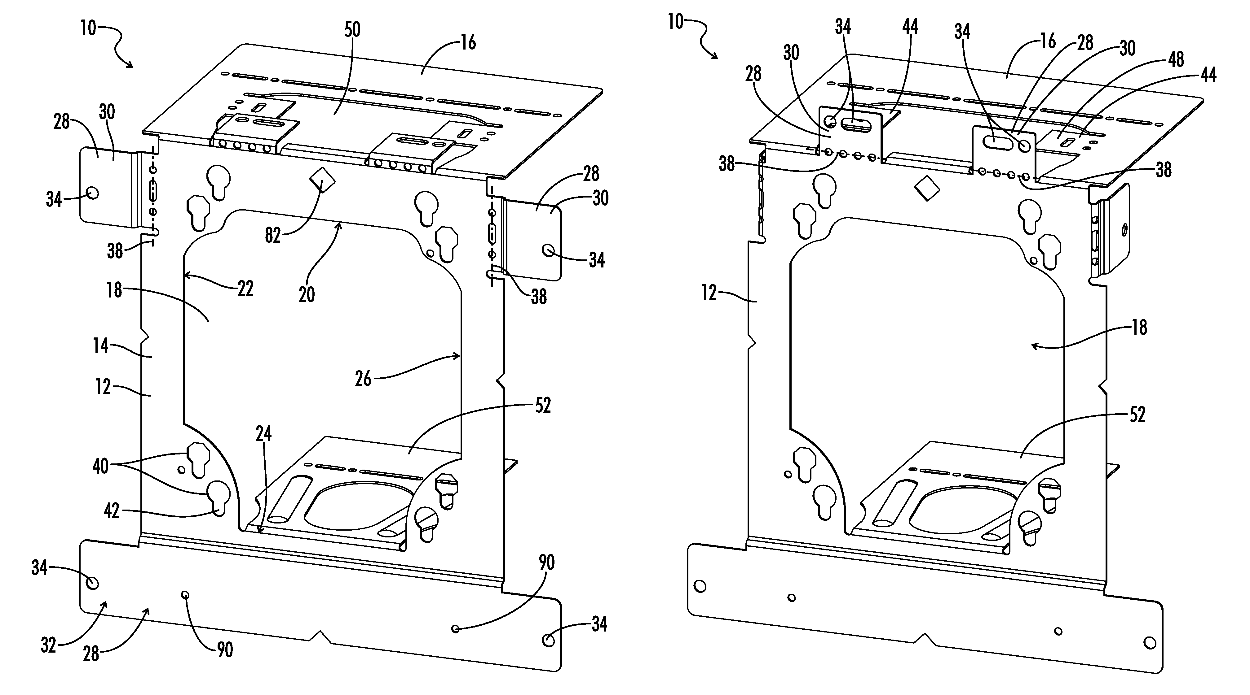
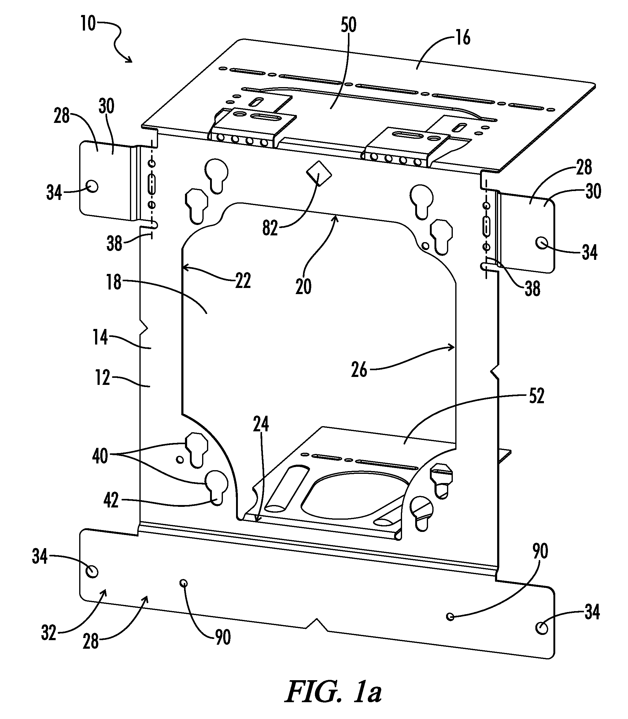
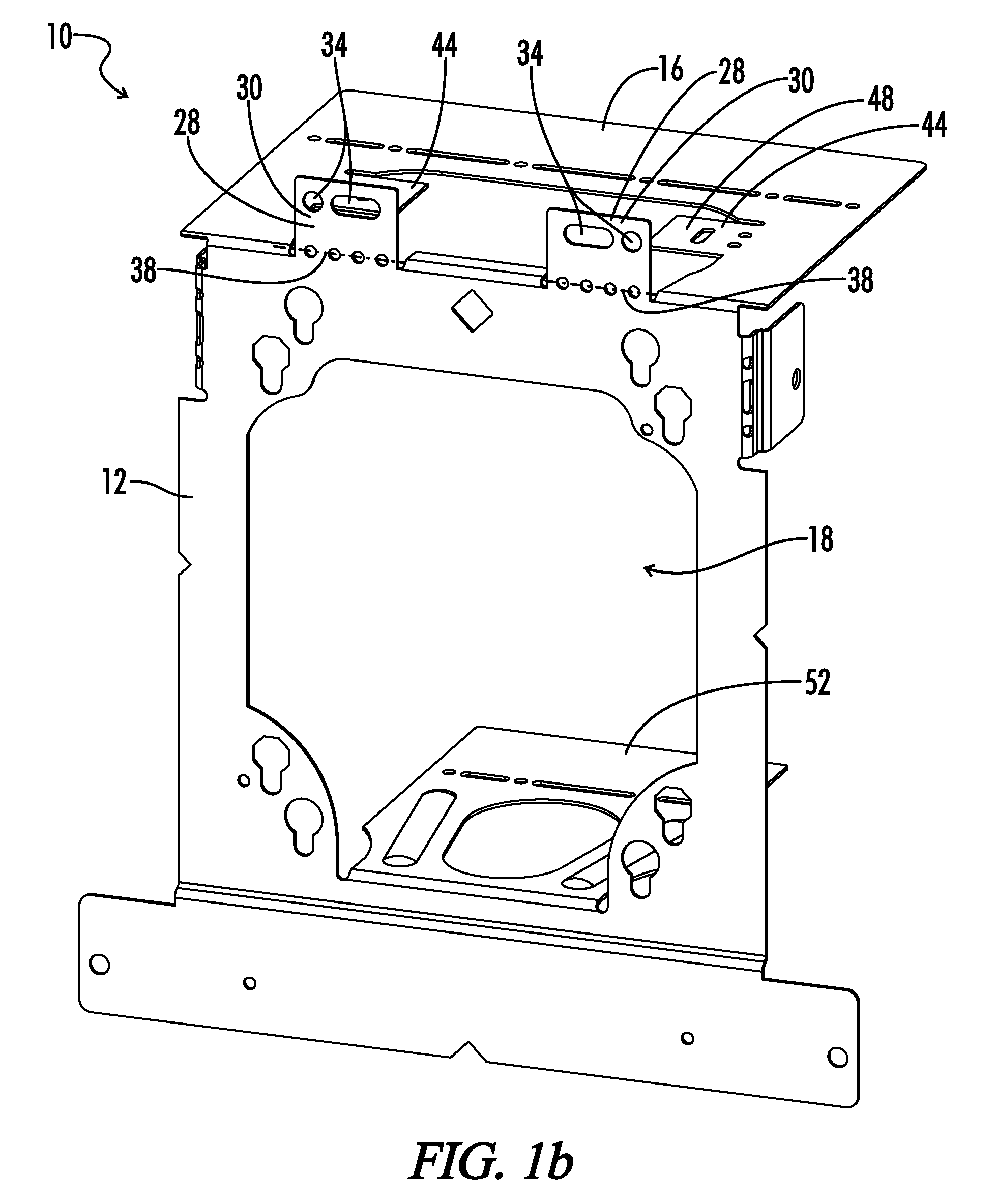
The present invention provides a mounting device for an electrical box that includes a bracket and a spanner bar. The spanner bar can be positioned vertically to set the desired height of the electrical box, and then the bracket can be mounted securely. The device also includes flexible locking tabs that can be folded into place to prevent slippage or disengagement of the electric box from the bracket. The technical effects of this invention include improved stability and secure mounting of electrical boxes in a variety of situations.

Problems solved by technology

The present invention aims to solve the problems of mounting electrical boxes on walls by providing a universal bracket that can be used for various applications, without requiring complex specifications and impractical locking devices. The bracket can accommodate various types and sizes of electric boxes, and can easily be installed in the field or pre-fabricated. The bracket can also prevent the electric box from slipping or becoming dislodged from its desired position prior to permanent fastening. Additionally, the invention provides a single mounting bracket that can accommodate one or more electric boxes in various locations, without requiring hand measurement by an electrician.

Method used


Image

  • Universal electric box mounting device
  • Universal electric box mounting device
  • Universal electric box mounting device

Examples


Embodiment Construction

[0045]Throughout the specification and claims, the following terms take at least the meanings explicitly associated herein, unless the context dictates otherwise. The meanings identified below do not necessarily limit the terms, but merely provide illustrative examples for the terms. The meaning of “a,”“an,” and “the” may include plural references, and the meaning of “in” may include “in” and “on.” The phrase “in one embodiment,” as used herein does not necessarily refer to the same embodiment, although it may. The term “plane” as used herein refers to an abstract reference plane or axis that may be locationally defined as collinear and / or coincident with a particular structure, but is not spatially limited thereby unless so specifically recited. The “orientation” of a bracket as used herein refers to the position of a particular portion of the bracket with respect to any other portion of the bracket, such as for example where a “top” and a “bottom” edge of the bracket may be define...


PUM


Abstract

A universal bracket is provided for mounting electrical boxes. The bracket includes a generally rectangular first plate having at least one aperture defined within the first plate. The aperture is shaped to provide access to an electrical box mounted to the first plate, and further includes first and second pairs of diagonally opposite corners. A second plate extends rearward and substantially perpendicular to the first plate and located proximate a first side of the aperture. The first plate further includes one or more fastening portions and a plurality of mounting holes disposed about the fastening portions. One or more of the mounting holes are positioned for mounting the bracket to a vertical structural member adjacent either of two opposite sides of the bracket or a horizontal element adjacent a third side of the bracket, maintaining a particular bracket orientation.

Description


Claims


Application Information

Patent Timeline
Owner RINDERER ERIC R
Learn More