
Security system

a security system and sensor technology, applied in the field of security systems, can solve problems such as the inability to use all sensors, and achieve the effect of reducing the nuisance of wiring

Inactive Publication Date: 2013-02-26
MIGHTY CUBE CO LTD
View PDF6 Cites 8 Cited by
  • Summary
  • Abstract
  • Description
  • Claims
  • Application Information

AI Technical Summary

Benefits of technology

The present invention allows for the wiring between a slave unit and a master unit to be eliminated while still keeping the arrangement convenient. This helps to reduce the nuisance of wiring and improves the overall performance of the system.

Problems solved by technology

If the merchandise items are arranged at wide intervals, the wires may be short, as indicated by 14B of FIG. 14, and it may be impossible to use all sensors.

Method used


Image

  • Security system
  • Security system
  • Security system

Examples


Embodiment Construction

[0031]A security system according to an embodiment of the present invention will now be described in detail with reference to the accompanying drawings.

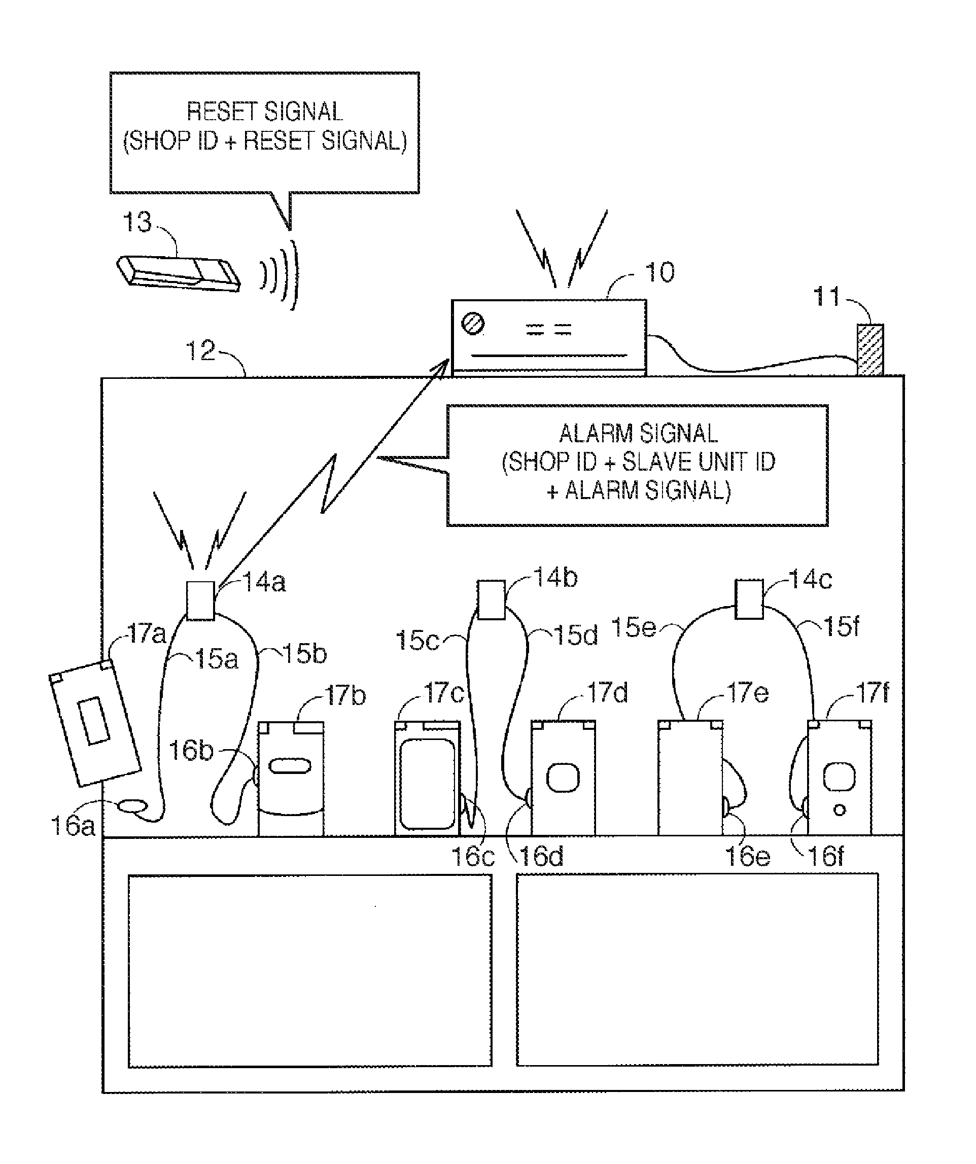
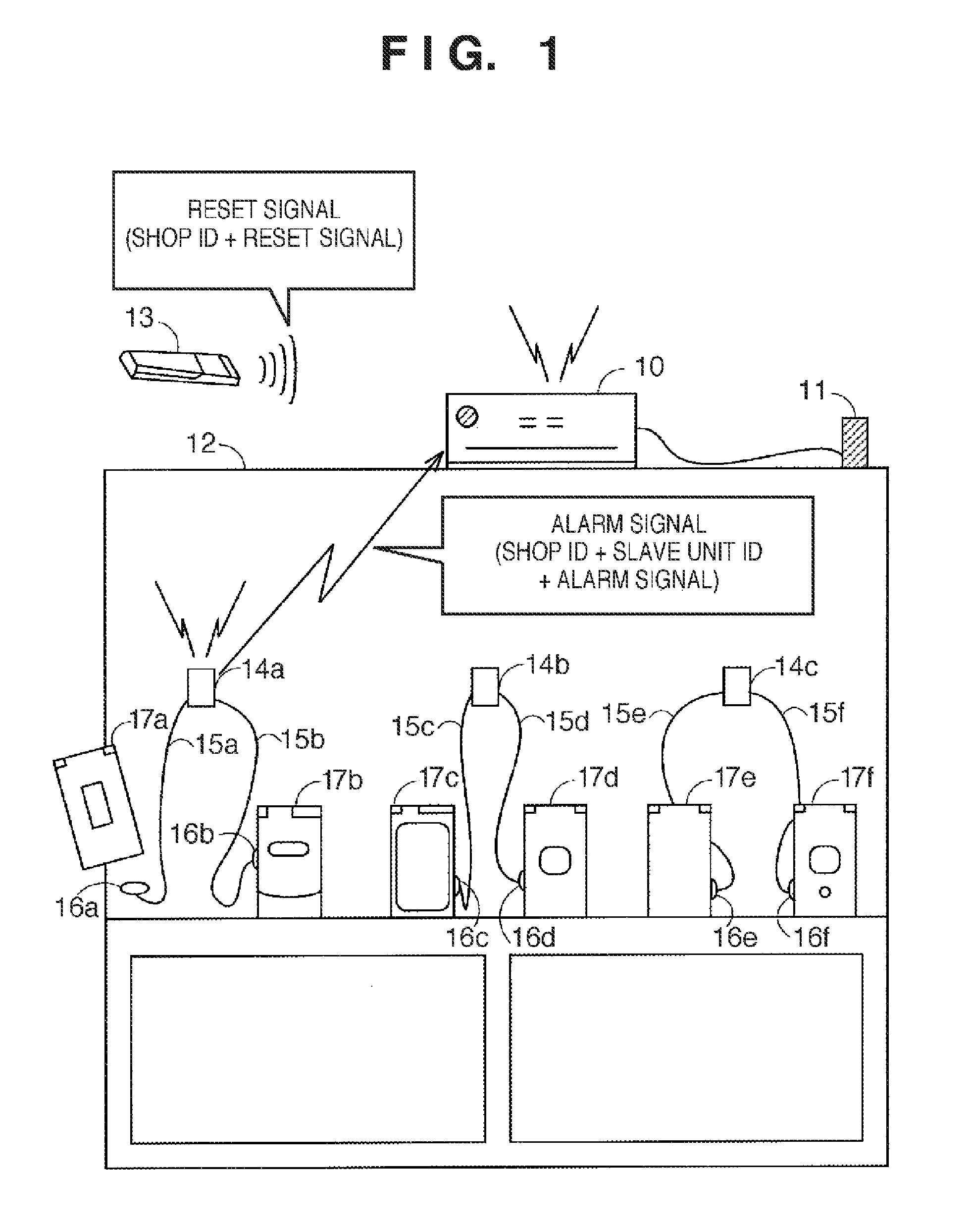
[0032]FIG. 1 is a view showing an example of a merchandise rack (merchandise display rack 12) at a shop using the security system. Note that the shop can be, for example, a large store such as a large consumer electronics retailer or a DIY store, a small shop such as a boutique or a variety store, or an exhibition hall. That is, the shop is not particularly limited as long as it lays out merchandise items (including exhibits) on merchandise racks.

[0033]The security system monitors theft of merchandise items placed on the merchandise racks at the shop. The shop is provided with the merchandise display rack 12 on which display merchandise items (cellular phones in this case) 17 (17a to 17f) are put on show. The plurality of display merchandise items 17 are arranged on the merchandise display rack 12 at a predetermined interval.

[0034]Se...


PUM


Abstract

A security system includes a sensor attached to a merchandise item, a slave unit attached to a merchandise rack and connected to one or a plurality of sensors via a wire, and a master unit that monitors theft of the merchandise item by wirelessly receiving a signal using a first frequency band from one or a plurality of slave units.

Description

BACKGROUND OF THE INVENTION[0001]1. Field of the Invention[0002]The present invention relates to a security system for monitoring theft of merchandise items placed on merchandise racks at a shop.[0003]2. Description of the Related Art[0004]A security system is known for monitoring theft of merchandise items for sale or display. In such a system, a sensor is attached to each merchandise item, and when detached, notifies a monitoring device of the detachment via a wire. In this case, the monitoring device gives an alarm in response to the notification from the sensor.[0005]The monitoring device (master unit) and the sensor are generally connected by a wire. A plurality of (for example, 10) sensors are connected to one monitoring device. For this reason, for example, if the merchandise items are arranged at narrow intervals, as indicated by 14A of FIG. 14, the wiring is a nuisance. If the merchandise items are arranged at wide intervals, the wires may be short, as indicated by 14B of F...

Claims


Application Information

Patent Timeline
Patent Type & Authority Patents(United States)
IPC IPC(8): G08B13/14
CPCG08B13/1463G08B13/1454A47F7/024G08B13/14G08B13/22G08B25/10G06K17/00
Inventor TATSUMI, ICHIDOMATSUI, KEIICHINOMA, YASUHIROSAITOH, AKIRAINUBUSHI, HIROFUMI
Owner MIGHTY CUBE CO LTD
Learn More