Switch with electrical member supported in elastic folded contact

a technology of electrical member and electrical member, which is applied in the direction of contacts, electrical apparatus, legends, etc., can solve the problems of bursting the fixing portion of the housing, and achieve the effect of increasing the assembly success ratio

Active Publication Date: 2013-02-26
HON HAI PRECISION IND CO LTD
View PDF3 Cites 2 Cited by
  • Summary
  • Abstract
  • Description
  • Claims
  • Application Information

AI Technical Summary

Benefits of technology

[0007]A primary object of the present invention is to provide a switch for increasing success ratio in assembly.
[0009]The LED always connects with the second terminal by the connecting contact, and the connecting contact defines the spring portion for the connecting contact to flexibly inserted in the fixing groove of the insulative housing and reducing the burst probability of the fixing groove. It is beneficial for switch to reliably reduce fraction defective in assembly.

Problems solved by technology

But due to this reason in assembly, the cantilevered arm of the LED may burst the fixing portion of the housing.

Method used


Image

  • Switch with electrical member supported in elastic folded contact
  • Switch with electrical member supported in elastic folded contact
  • Switch with electrical member supported in elastic folded contact

Examples


Embodiment Construction

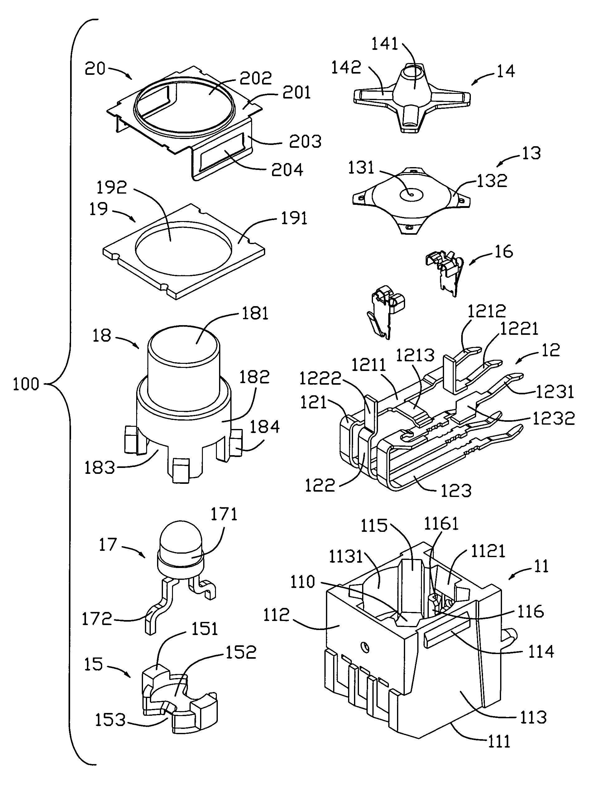
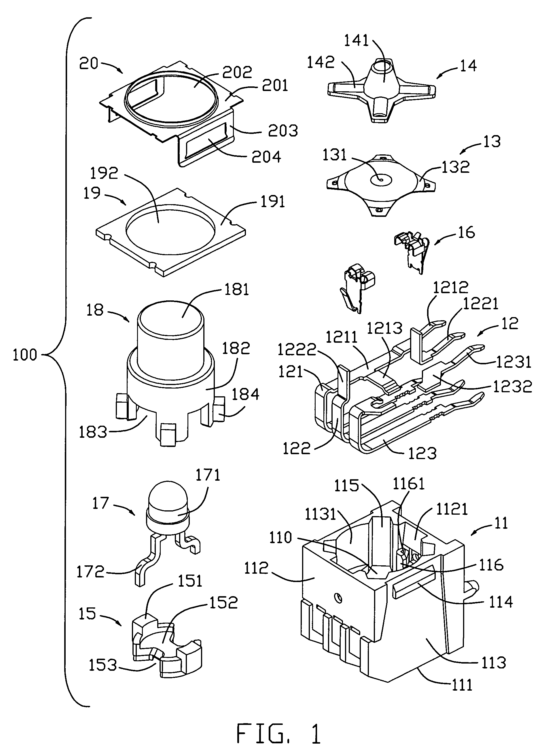
[0015]Reference will now be made to the drawing figures to describe the present invention in detail. Referring to FIG. 1, a switch 100 in accordance with the preferred embodiment of the present invention is adapted for electrically connecting with an electrical member 17, also called the LED 17. In fact, the switch 100 may also be used for other kinds of electrical member in other embodiments. The switch 100 comprises an insulative housing 11 defining a cavity 110, a plurality of fixed terminals 12 embedded in the insulative housing 11, a movable contact 13 retained in the cavity 110 of the insulative housing 11, an operator 14 exposed above the movable contact 13, a retention member 15 positioned on the operator 14, a pair of intermediate connecting contacts 16, also called the elastic folded contact 16, respectively defined on either hand of the retention member 15, an LED 17 located above the retention member 15, an actuator 18 assembled to the insulative housing 11, a cover 20 a...


PUM


Abstract

A switch at least comprises a housing, an electrical member, a terminal and a connecting contact. The housing defining a cavity that includes two opposite sidewalls, and a pair of fixing grooves each defined by said sidewall and an extension wall spaced from said sidewall. The electrical member having a pair of leads disposed within said cavity. The terminal retained in the housing and having a contact portion abutting against said sidewall. The connecting contact retainably disposed within each said groove, and the connecting contact has a plate base abutting against said extension wall, a fixing portion attached onto an upper end of the plate base for clamping each said lead of the electrical member, and an spring portion reversely extending from an opposite bottom end of the plate base and designed to mechanically and electrically engage the contact portion of the second terminal.

Description

BACKGROUND OF THE INVENTION[0001]1. Field of the Invention[0002]The present invention relates to a switch, and particularly to a switch provided with an electrical member such as a Light Emitting Diode (LED), used in various electronic devices.[0003]2. Description of Related Art[0004]A conventional switch provided with a light source is described in U.S. Pat. No. 7,202,429 published on Apr. 10, 2007 and U.S. Pat. No. 7,331,805 published on Feb. 19, 2008. The U.S. Pat. No. 7,202,429 disclose a switching device, includes a vertically moveable operating member with a cavity in which a light lies. The light is supported on tongues of a pair of sheet metal energizing members. Each energizing member has laterally opposite sides that form a pair of legs. The legs extend downward along opposite sides of the switch casing, and the legs have lugs at their lower ends for soldering to traces on a circuit board. The U.S. Pat. No. 7,331,805 disclose a switch, comprises an insulative housing defin...

Claims


Application Information

Patent Timeline
Patent Type & Authority Patents(United States)
IPC IPC(8): H01H1/14H01H13/14
CPCH01H13/023H01H13/48H01H2001/5888H01H2219/04
Inventor HU, YONG-HUI
Owner HON HAI PRECISION IND CO LTD
Why Eureka
Try Eureka