
Method and apparatus for low-bulk toughened fabrics for low-pressure molding processes

a low-pressure molding and fabric technology, applied in the field of non-crimped fabrics, can solve the problems of low bulk, fiber spreading, and inability to meet the requirements of low-pressure molding, and achieve the effects of reducing the number of raw materials

Active Publication Date: 2013-02-12
THE BOEING CO
View PDF26 Cites 14 Cited by
  • Summary
  • Abstract
  • Description
  • Claims
  • Application Information

AI Technical Summary

Benefits of technology

The present patent describes a method and apparatus for manufacturing a composite fabric by laying down a unidirectional lay-up of fibers and a porous bonding layer to form a unidirectional composite tape. The tape is then heated and pressure applied to form a unidirectional composite tape that maintains the fibers in a desired configuration. The unidirectional composite tape is slit and a first plurality of lengths of the tape is laid down to form a first layer of the composite fabric. A second plurality of lengths of the tape is laid down on the first layer at a predetermined angle to form a second layer of the composite fabric. The first and second layers are consolidated to form a continuous composite fabric. Resin is then introduced into the fabric to form a composite component. The technical effects of this patent include improved methods and apparatus for manufacturing composite fabrics with improved strength and flexibility.

Problems solved by technology

Further, composite materials may provide longer service life for various components in an aircraft.
This type of process normally works well except, in some cases, a particular part may be too large for an autoclave or may require an expensive autoclave that is large enough to fit the part.
These types of processes, however, may not have the desired quality, low bulk, or fiber spreading when producing composite components with low-pressure molding processes when an interlayer material is introduced between the plies.

Method used


Image

  • Method and apparatus for low-bulk toughened fabrics for low-pressure molding processes
  • Method and apparatus for low-bulk toughened fabrics for low-pressure molding processes
  • Method and apparatus for low-bulk toughened fabrics for low-pressure molding processes

Examples


Embodiment Construction

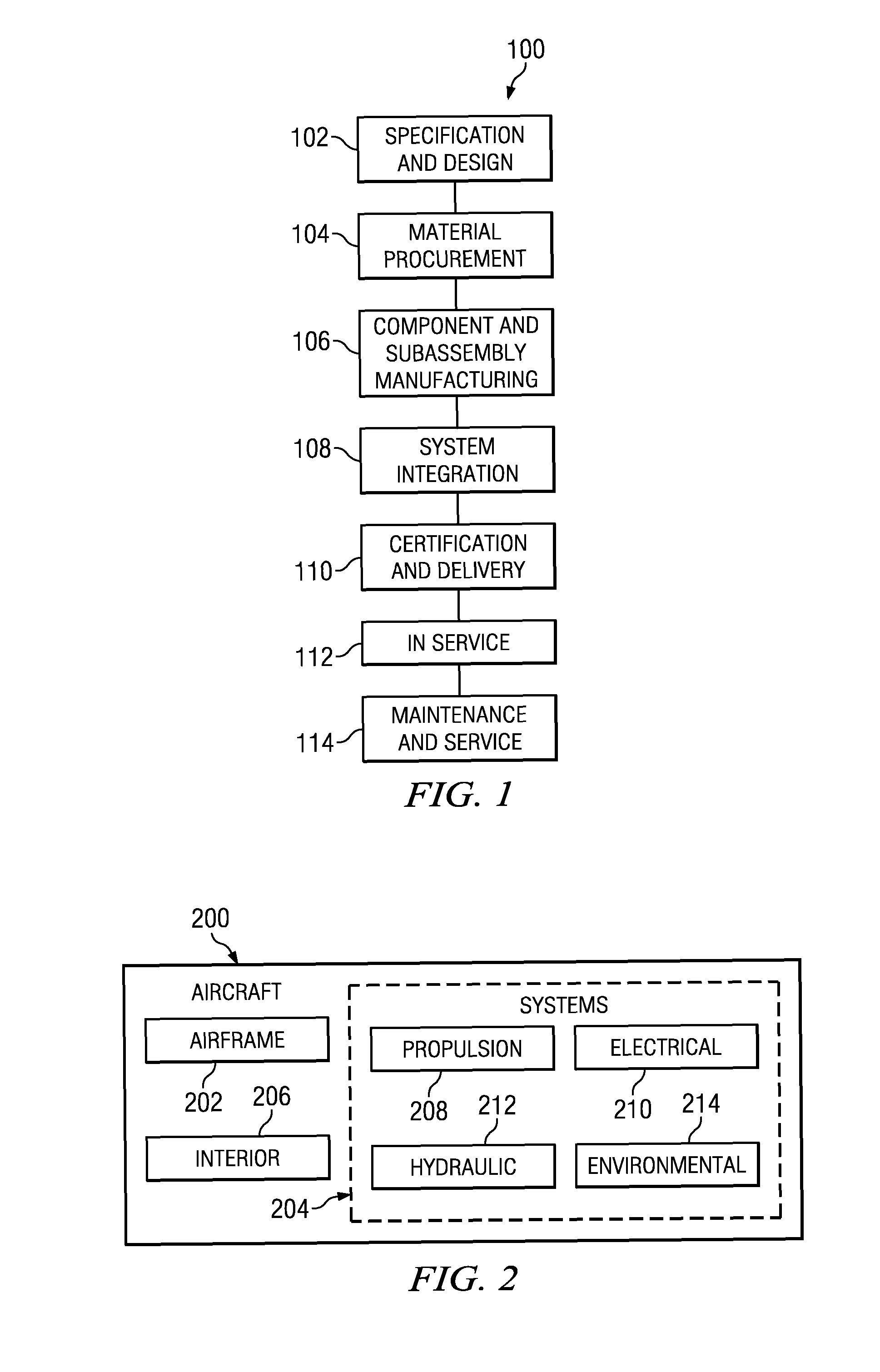
[0031]Referring more particularly to the drawings, embodiments of the disclosure may be described in the context of aircraft manufacturing and service method 100 as shown in FIG. 1 and aircraft 200 as shown in FIG. 2. Turning first to FIG. 1, an illustration of an aircraft manufacturing and service method is depicted in accordance with an advantageous embodiment. During pre-production, aircraft manufacturing and service method 100 may include specification and design 102 of aircraft 200 in FIG. 2 and material procurement 104.

[0032]During production, component and subassembly manufacturing 106 and system integration 108 of aircraft 200 in FIG. 2 takes place. Thereafter, aircraft 200 in FIG. 2 may go through certification and delivery 110 in order to be placed in service 112. While in service by a customer, aircraft 200 in FIG. 2 is scheduled for routine maintenance and service 114, which may include modification, reconfiguration, refurbishment, and other maintenance or service.

[0033]...


PUM

PropertyMeasurementUnit
Lengthaaaaaaaaaa
Thicknessaaaaaaaaaa
Angleaaaaaaaaaa

Abstract

A method and apparatus for manufacturing. A fiber layer and a first porous bonding layer are formed to form a unidirectional lay-up of fibers. The unidirectional lay-up of fibers is heated under pressure to form a unidirectional composite tape. A first plurality of lengths of the unidirectional composite tape is laid down to build a first layer from the unidirectional composite tape. A second plurality of lengths of the unidirectional composite tape is laid down to build a second layer from the unidirectional composite tape on the first layer at a predetermined angle from the first layer. At least one of the first and second plurality of lengths of the unidirectional composite tape are slit while laying down the first and second plurality of lengths of the unidirectional composite tape. A composite fabric is formed from the first and second layer.

Description

CROSS-REFERENCE TO RELATED APPLICATION[0001]This application is a continuation-in-part of patent application U.S. Ser. No. 11 / 937,010, filed Nov. 8, 2007, entitled “Method and Apparatus for Low-Bulk Toughened Fabrics for Low-Pressure Molding Processes”, which is incorporated herein by reference.BACKGROUND INFORMATION[0002]1. Field[0003]The present disclosure relates generally to non-crimped fabrics and, in particular, to a method and apparatus for manufacturing low-bulk, non-crimped fabrics. Still more particularly, the present disclosure relates to a method and apparatus for creating composite materials from low-bulk, non-crimped fabrics.[0004]2. Background[0005]Aircraft are being designed and manufactured with greater and greater percentages of composite materials. Some aircraft may have more than 50 percent of their primary structure made from composite materials. Composite materials may be used in aircraft to decrease the weight of the aircraft. This decreased weight may improve...

Claims


Application Information

Patent Timeline
IPC IPC(8): B29C70/38B29C65/02
CPCB29C70/386B29C70/42D04B21/165D04B23/10B29C70/202B29B11/16Y10T156/1067Y10T156/1074
Inventor TSOTSIS, THOMAS KARL
Owner THE BOEING CO
Learn More