
Spindle motor and disk driver having the same

a technology of spindle motor and disk drive, which is applied in the direction of data recording, magnetic circuit shape/form/construction, instruments, etc., can solve the problems of degrading the assembly and rotation characteristics increasing the noise and vibration levels accordingly, and unstable spindle motor behaviour, etc., to achieve the effect of improving rigidity and ensuring the assembly and rotational stability of the spindle motor

Inactive Publication Date: 2013-02-05
SAMSUNG ELECTRO MECHANICS CO LTD
View PDF24 Cites 4 Cited by
  • Summary
  • Abstract
  • Description
  • Claims
  • Application Information

AI Technical Summary

Benefits of technology

This design stabilizes the spindle motor's rotation, reduces noise and vibration, prevents oil leakage, and enhances assembly and rotation stability, thereby reducing power consumption and maintaining rigidity.

Problems solved by technology

However, since rotating members should be manufactured to be thin, the adhesion between components of the rotating members is degraded, which makes it difficult to assemble the rotating members, causes undesirable rotation characteristics such as vertical vibrations, bending vibrations, and the like, and degrades the assembly and rotation characteristics of the spindle motor due to an external impact applied to the spindle motor or a force applied when the disk is loaded onto and removed therefrom.
In addition, since an axial gap between the rotating members and the fixing members of the spindle motor is small, the air flow turbulence occurs between the rotating members and the fixing members when the rotating members are rotated, and the noise and vibration levels are increased accordingly.
The air flow turbulence causes the unstable behaviour of the spindle motor and the leakage of oil from the bearing member when the spindle motor is in rotation.
In addition, the unstable operation of the spindle motor generates a large amount of heat from the fixing members and degrades the efficiency of the spindle motor to increase the power consumption thereof.

Method used


Image

  • Spindle motor and disk driver having the same
  • Spindle motor and disk driver having the same
  • Spindle motor and disk driver having the same

Examples


Embodiment Construction

[0076]Exemplary embodiments of the present invention will now be described in detail with reference to the accompanying drawings. The invention may however be embodied in many different forms and should not be construed as limited to the embodiments set forth herein. Rather, these embodiments are provided so that this disclosure will be thorough and complete, and will fully convey the scope of the invention to those skilled in the art. In the drawings, the shapes and dimensions may be exaggerated for clarity, and the same reference numerals will be used throughout to designate the same or like components.

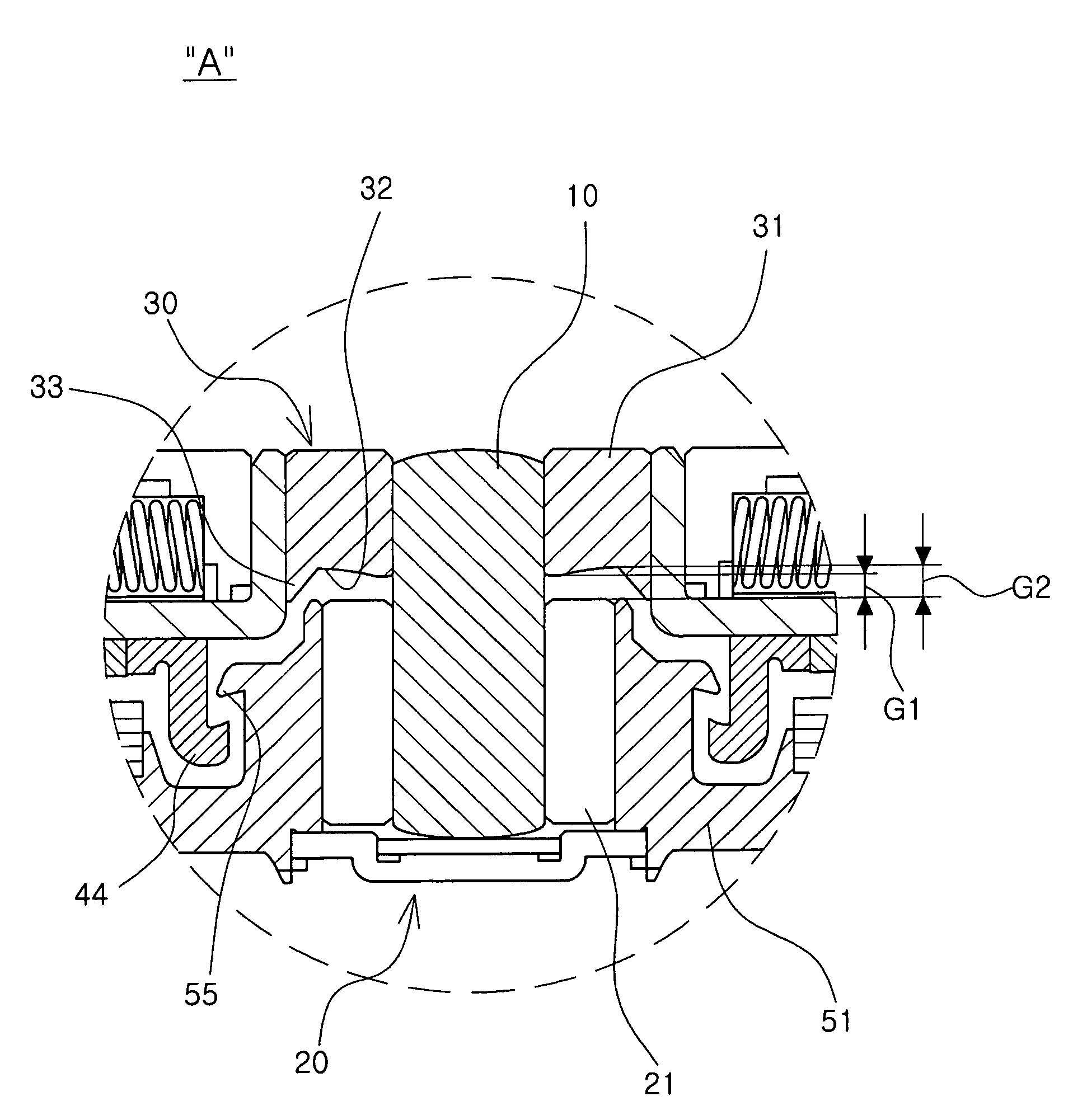
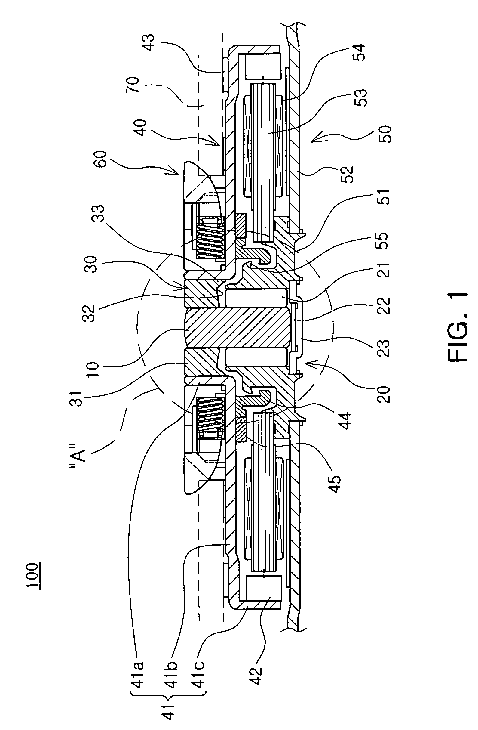
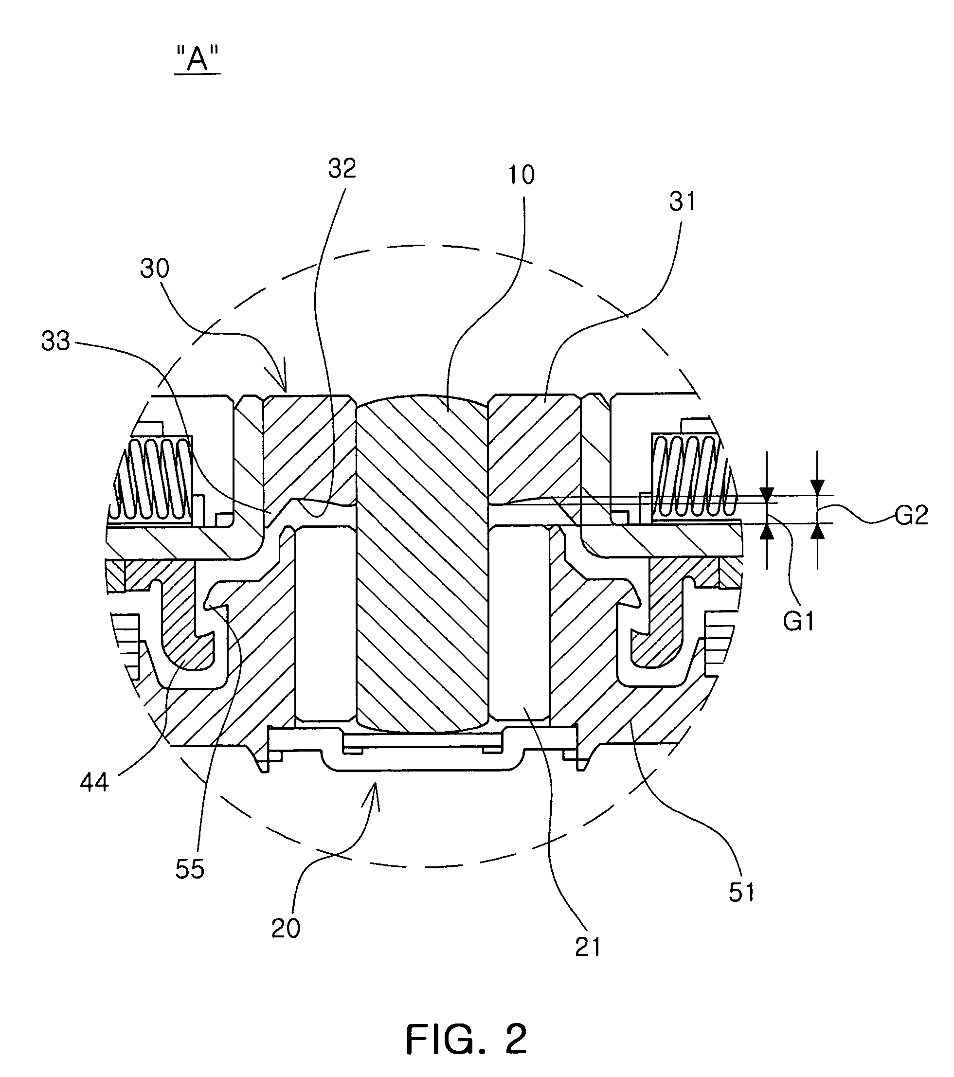
[0077]FIG. 1 is an axial cross-sectional view of a disk driver according to a first exemplary embodiment of the present invention, FIG. 2 is an enlarged view showing part A of FIG. 1, FIG. 3 is a plan view, an axial cross-sectional view, and a bottom view showing a bush, and FIG. 4 is an upper perspective view of a bush.

[0078]Referring to FIGS. 1 and 2, a disk driver 100 according t...


PUM

PropertyMeasurementUnit
outer diameteraaaaaaaaaa
outer-diameteraaaaaaaaaa
inner-diameteraaaaaaaaaa

Abstract

Disclosed herein is provided a spindle motor and a disk driver having the same. There is provided a spindle motor including: a sleeve rotatably supporting a shaft; a bush combined with the top portion of the shaft to be rotated together with the shaft; a rotor case including a cylindrical wall part combined with the outer peripheral surface of the bush; an air flow spreading part formed on the axial bottom part of the bush and spreading the air flow generated between the shaft and the sleeve to the radial outer side when the shaft is rotated; and a sealing part formed on the axial bottom portion of the bush and formed between the cylindrical wall part and the air flow spreading part to seal oil when the shaft is rotated.

Description

CROSS-REFERENCE TO RELATED APPLICATIONS[0001]This application claims the priority of Korean Patent Application No. 10-2010-0079984 filed on Aug. 18, 2010, and Korean Patent Application No. 10-2010-0079987 filed on Aug. 18, 2010 in the Korean Intellectual Property Office, the disclosures of which are incorporated herein by reference.BACKGROUND OF THE INVENTION[0002]1. Field of the Invention[0003]The present invention relates to a spindle motor and a disk driver having the same, and more particularly, to a spindle motor capable of preventing air flow turbulence, caused when a shaft is rotated, and oil leakage and securing the assembly and rotation stability of a spindle motor from external impact applied to the spindle motor or force applied when a disk is loaded and removed.[0004]2. Description of the Related Art[0005]An apparatus for driving an optical disk-type recording medium is configured to read and write signals by moving an optical pickup device while loading a recording medi...

Claims


Application Information

Patent Timeline
Patent Type & Authority Patents(United States)
IPC IPC(8): G11B17/02
CPCG11B19/2009H02K1/30
Inventor SMIRNOV, VIATCHESLAVYOO, HO JUNCHOI, YEOLKIM, NAM SEOK
Owner SAMSUNG ELECTRO MECHANICS CO LTD
Learn More