
Apparatus for adjustable wrapping

a technology of adjustable wrapping and accessories, applied in the field of packaging, can solve the problems of inherent practical limitations, further limit the overall processing speed or indwelling time of products at or within the wrapping station,

Inactive Publication Date: 2013-01-22
DOUGLAS MACHINE LIABILITY
View PDF27 Cites 6 Cited by
  • Summary
  • Abstract
  • Description
  • Claims
  • Application Information

AI Technical Summary

Benefits of technology

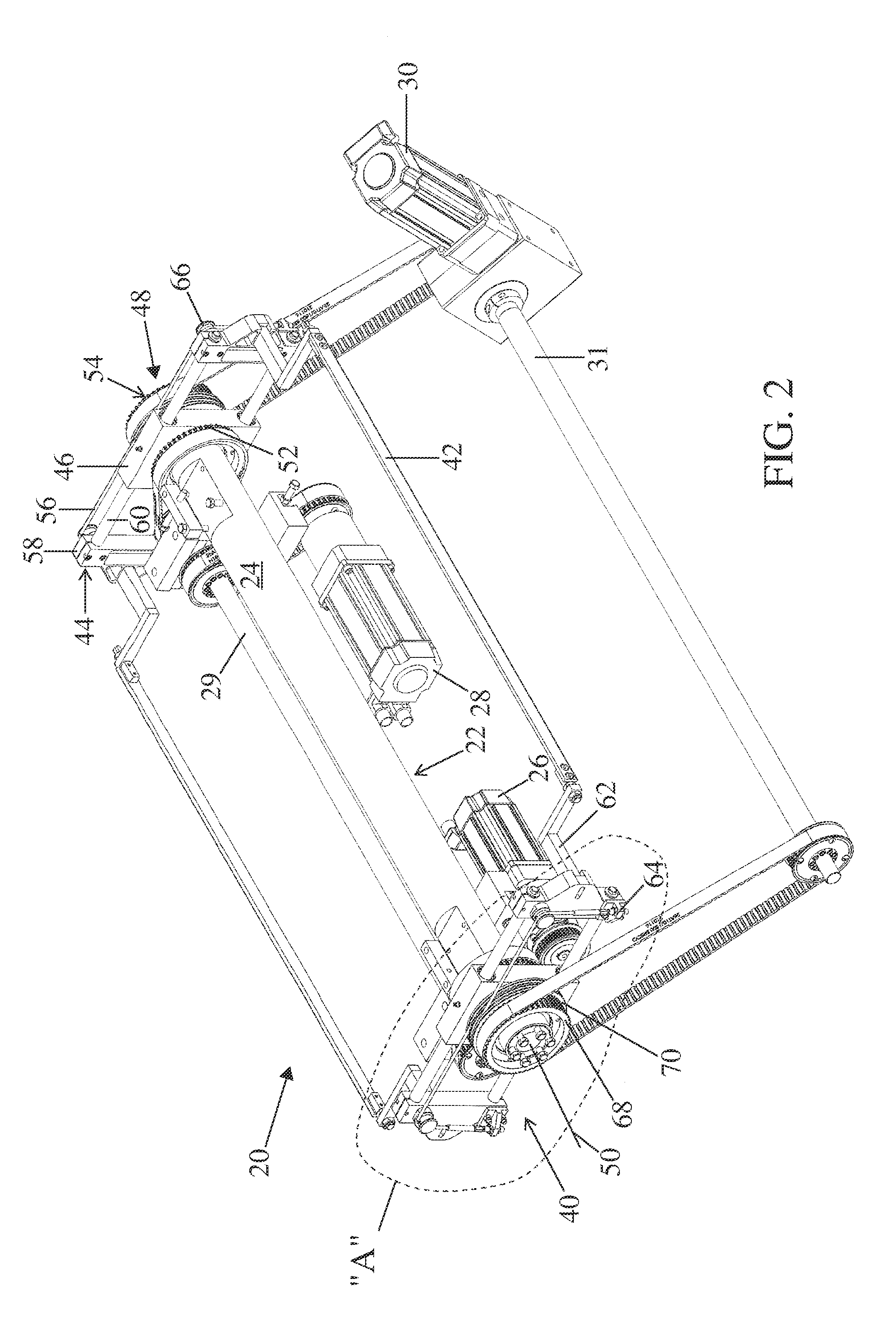
This patent describes a system for wrapping a product with a sheet of material. The system includes a wrap bar that is directed and guided by a wrap bar carrier, which is driven to rotate about a central axis. The spacing between the wrap bar and the product is adjusted to fit the product profile. The system also includes a sheet supporting member that is supported by the wrap bar carriers, which allows it to travel without a track. The method involves rotating the wrap bar about the product and adjusting its translation to match the profile of the product. Overall, this system provides a way to efficiently and accurately wrap products.

Problems solved by technology

For example, and in contradistinction to chain drives, while the cam track approach generally permits advantageous select velocity and acceleration changes for the wand during its orbit, inherent practical limitations exist owing to the interface of the track follower with the cam track.
Moreover, the noted inherent practical limitations further limit the overall processing speed or indwelling time of product at or within the wrapping station (i.e., the period of the orbit).

Method used


Image

  • Apparatus for adjustable wrapping
  • Apparatus for adjustable wrapping
  • Apparatus for adjustable wrapping

Examples


Embodiment Construction

[0019]Prior to a description of any apparatus, system or process particulars, some preliminary remarks are in order. More particularly, several functional or operative notions warrant review, and / or previewing as the case may be.

[0020]By way of review, generally, a wand or wrapping support element is driven for travel in the direction of product conveyance. Via rotation, such wand, in an side / end view travels a first 180° arcuate path over a product receiving conveyor table and continues through a second 180° arcuate path under or below the table to thus generally define a 360° wand orbit. While circular orbits (i.e., constant radius paths) perhaps serve and have served some product wrapping scenarios well, other orbit profiles, e.g., elliptical or polygonal, require select departures / changes in the elevation of the wand relative to the conveyor table, more particularly in relation to a wrapping mechanism axis of rotation. In summary, known wrapping apparatus, systems and / or process...


PUM

PropertyMeasurementUnit
rotationaaaaaaaaaa
radial distanceaaaaaaaaaa
lengthaaaaaaaaaa

Abstract

A wrapping apparatus, system, station and / or process is generally provided. As to the apparatus, it includes a wrap bar for engaging and directing a wrapper about the product, a wrap bar carrier from which the wrap bar extends, and a drive assembly operatively linked to the wrap bar carrier. The carrier block, which translatingly retains the carrier intermediate opposing end portions thereof, is adapted for driven rotation about a wrapping axis of the apparatus so as to thereby rotatingly drive the bar about the axis via rotation of the carrier. The drive assembly, which is operatively linked to the carrier, selectively translates the carrier in relation to the carrier block during driven rotation of the carrier such that a radial distance for the bar from the axis is thereby capable of selective establishment in furtherance of delimiting a wrap bar travel path commensurate with the product profile of the product.

Description

TECHNICAL FIELD[0001]The present invention generally relates to the field of packaging, more particularly, to any or all of apparatus, systems, and processes, to aid product wrapping, and more particularly still, to apparatus, systems, and processes for wrapping a wide variety of products characterized by a wide variety of product profiles, for example and without limitation, any and all of cans, bottles, jars, cartons, trays, etc.BACKGROUND OF THE INVENTION[0002]Sleeve type wrapping stations are commonly part and parcel of automated packaging systems, namely, those characterized by the conveyance of product, usually, but not necessarily, an aggregation of discrete product elements, e.g., cans, bottles, jars, cartons, trays, etc. which are to be wrapped in furtherance of consolidating or securing the aggregation as a bundle or the like. Generally, conveyed product is received upon a conveyor of a wrapping station, with a leading edge of a wrapper or wrapping (i.e., a film sheet or t...

Claims


Application Information

Patent Timeline
Patent Type & Authority Patents(United States)
IPC IPC(8): B65B11/02
CPCB65B11/10B65B11/06
Inventor FLODING, DANIEL L.LUKANEN, JR., RICHARD W.
Owner DOUGLAS MACHINE LIABILITY
Learn More