
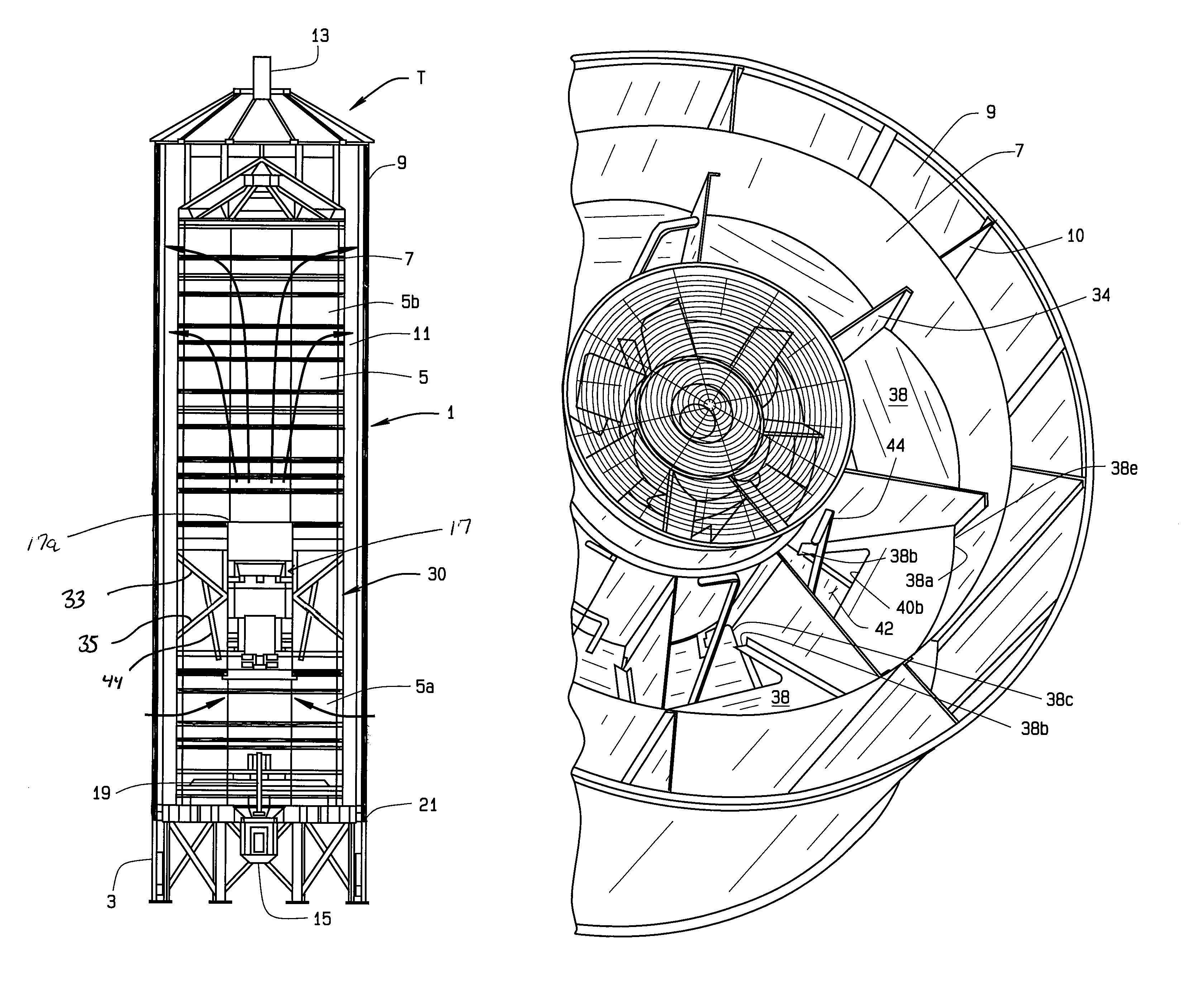
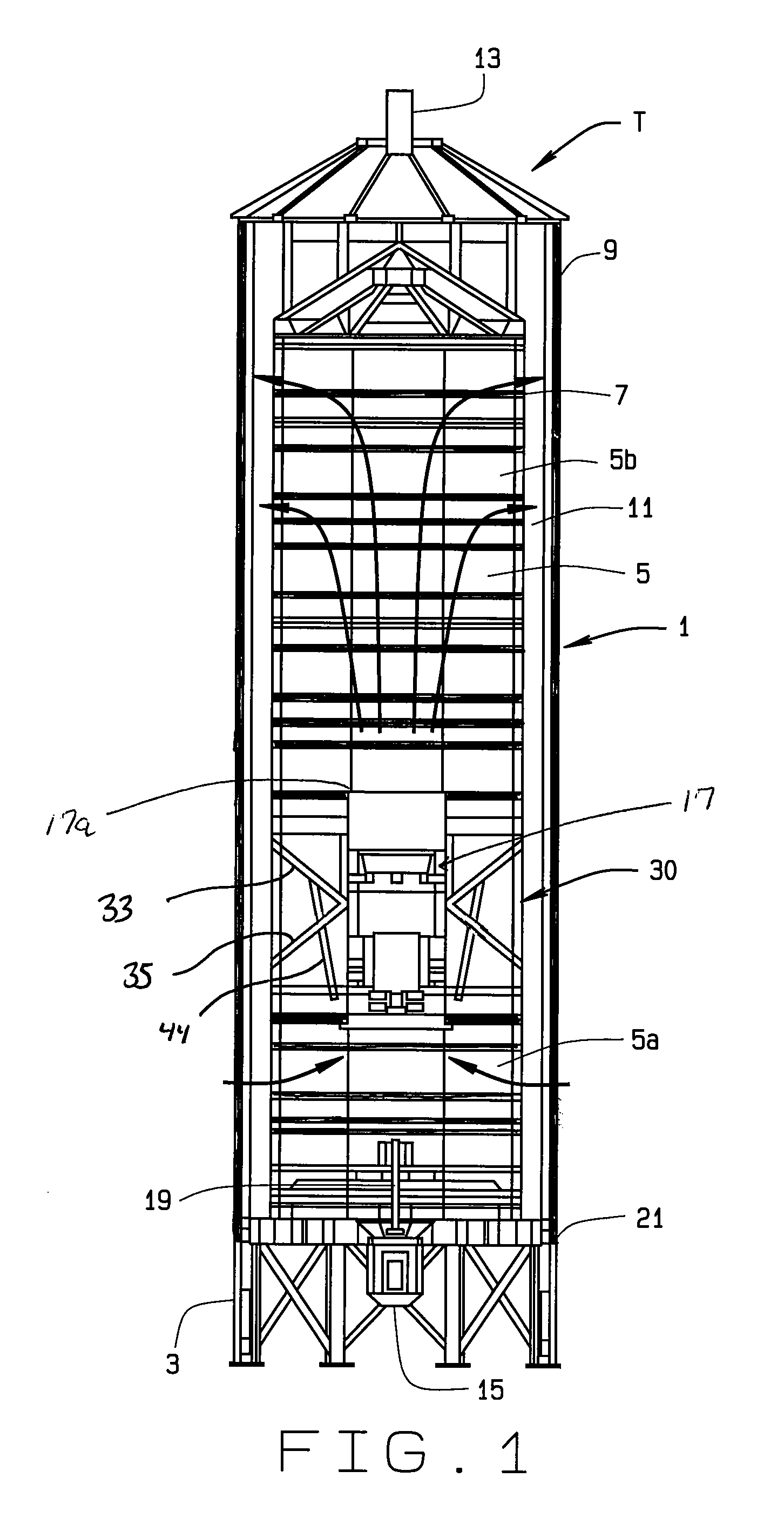
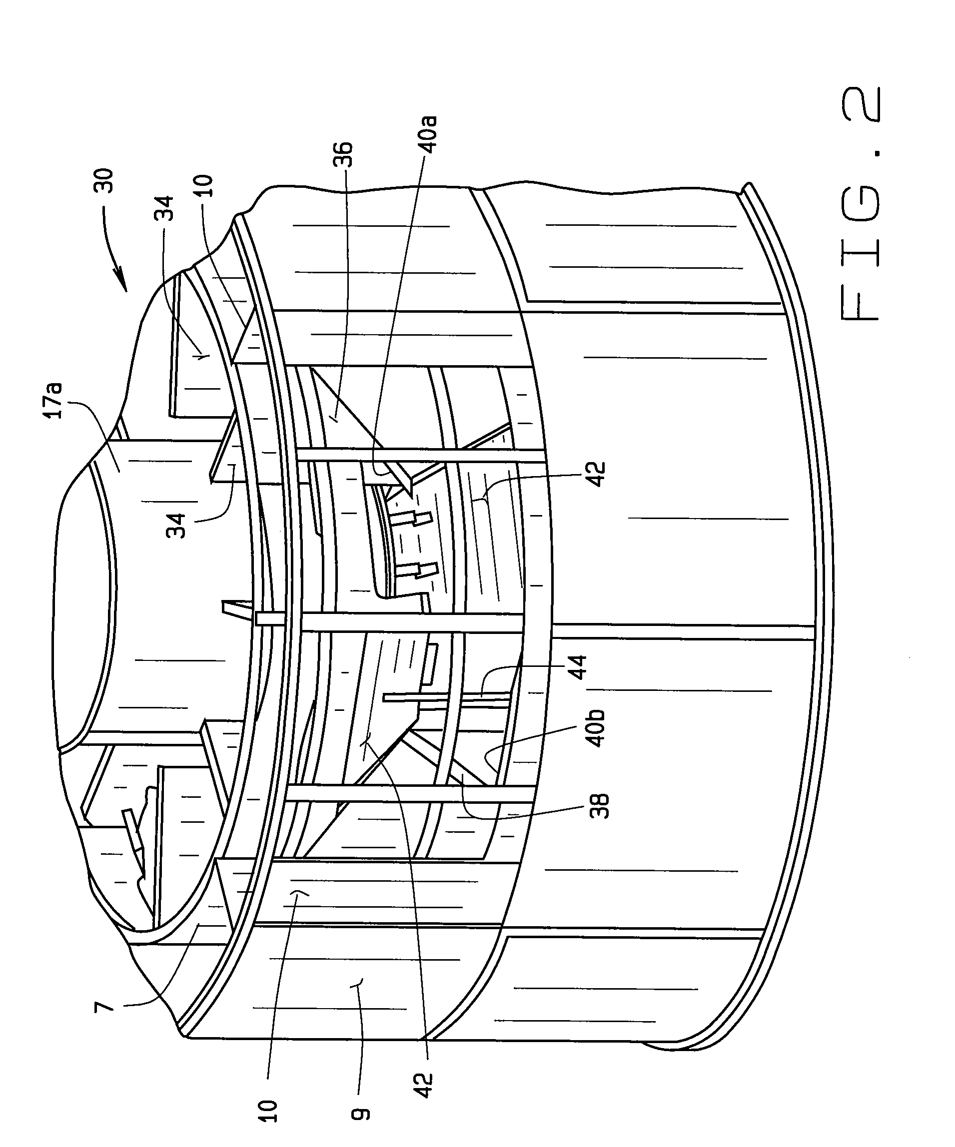
Adjustable divider/hopper for a grain tower dryer

a technology of tower dryer and hopper, which is applied in the direction of separation process, furnace, instruments, etc., can solve the problem that the hopper has not been installed in the dryer with the plenum

Active Publication Date: 2013-01-22
THE GSI GRP LLC
View PDF33 Cites 22 Cited by
  • Summary
  • Abstract
  • Description
  • Claims
  • Application Information

AI Technical Summary

Benefits of technology

Enables adjustable heating to cooling section ratios and effective particulate matter management, reducing stress on grains during drying and preventing accumulation, thereby improving drying efficiency and grain quality.

Problems solved by technology

However, to our knowledge, such hoppers have not been installed in dryers with plenum dividers.

Method used


Image

  • Adjustable divider/hopper for a grain tower dryer
  • Adjustable divider/hopper for a grain tower dryer
  • Adjustable divider/hopper for a grain tower dryer

Examples


Embodiment Construction

[0022]The following detailed description illustrates the claimed invention by way of example and not by way of limitation. This description will clearly enable one skilled in the art to make and use the claimed invention, and describes several embodiments, adaptations, variations, alternatives and uses of the invention, including what we presently believe is the best mode of carrying out the claimed invention. Additionally, it is to be understood that the claimed invention is not limited in its application to the details of construction and the arrangements of components set forth in the following description or illustrated in the drawings. The claimed invention is capable of other embodiments and of being practiced or being carried out in various ways. Also, it is to be understood that the phraseology and terminology used herein is for the purpose of description and should not be regarded as limiting.

[0023]A cylindrical tower grain dryer T is shown in partial cross-section in FIG. ...


PUM

PropertyMeasurementUnit
heightaaaaaaaaaa
lengthaaaaaaaaaa
pressureaaaaaaaaaa

Abstract

A combined plenum divider / hopper is provided for a grain drying tower. The divider / hopper is positioned in the drying tower proximate the heater for the drying tower and is operable to adjust the ratio of the length of the heating portion of the plenum to the length of the cooling portion of the plenum.

Description

CROSS-REFERENCE TO RELATED APPLICATIONS[0001]This application is a non-provisional of U.S. App. No. 61 / 158,062 filed Mar. 9, 2009, entitled “Adjustable Divider Hopper For A Grain Tower Dryer”, and which is incorporated herein by reference.STATEMENT REGARDING FEDERALLY SPONSORED RESEARCH OR DEVELOPMENT[0002]Not Applicable.BACKGROUND[0003]This application relates to tower grain dryers, and, in particular to a tower dryer in which the function of plenum adjustment ratio and divider / hopper is combined in a single unit.[0004]A grain tower dryer typically comprises a central plenum defined by a porous (or air pervious) wall. The tower also includes an outer porous (or air pervious) wall spaced from the plenum wall. The plenum wall and outer wall define an annular column through which grain to be dried fall. A heater / blower is typically positioned within the plenum. The heater / blower draws cool air in through a bottom portion of the grain column and expels heated air out through an upper p...

Claims


Application Information

Patent Timeline
Patent Type & Authority Patents(United States)
IPC IPC(8): F26B3/14
CPCF26B17/124
Inventor MORRISON, DAVIDFRANKOVICH, JOHN M.
Owner THE GSI GRP LLC
Learn More