Rod coupling having a pin

a technology of rod coupling and pin, which is applied in the direction of rod connection, coupling, borehole/well accessories, etc., can solve the problem of a relatively long time for threaded connections, and achieve the effect of simplifying or more broadly applicable rod coupling

Active Publication Date: 2012-12-25
TRACTO TECHN
View PDF22 Cites 2 Cited by
  • Summary
  • Abstract
  • Description
  • Claims
  • Application Information

AI Technical Summary

Benefits of technology

[0011]It is an object of the invention to provide a simplified or more broadly applicable rod coupling for horizontal boring.

Problems solved by technology

Aside from the problem that screwing the threaded connections takes a relatively long time and requires clean threads, such connections are particularly disadvantageous in that they allow for rod assembly rotation during the boring progress in one direction only.
In contrast to screw couplings, when using plug-in couplings, the problem of fixing the coupling in the coupling mouth after plug-in must be solved since the adhesion-based fixation possibility for the screw threads is not available.

Method used


Image

  • Rod coupling having a pin
  • Rod coupling having a pin
  • Rod coupling having a pin

Examples


Embodiment Construction

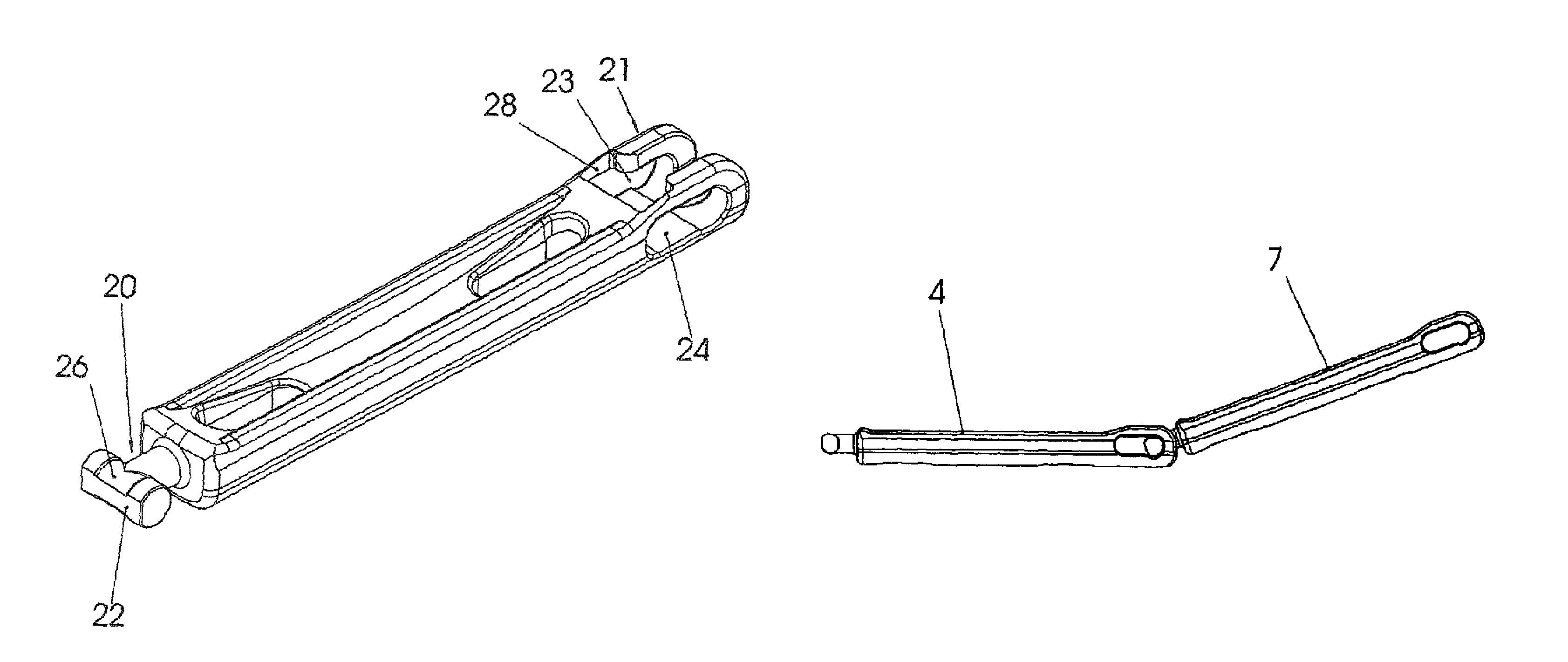
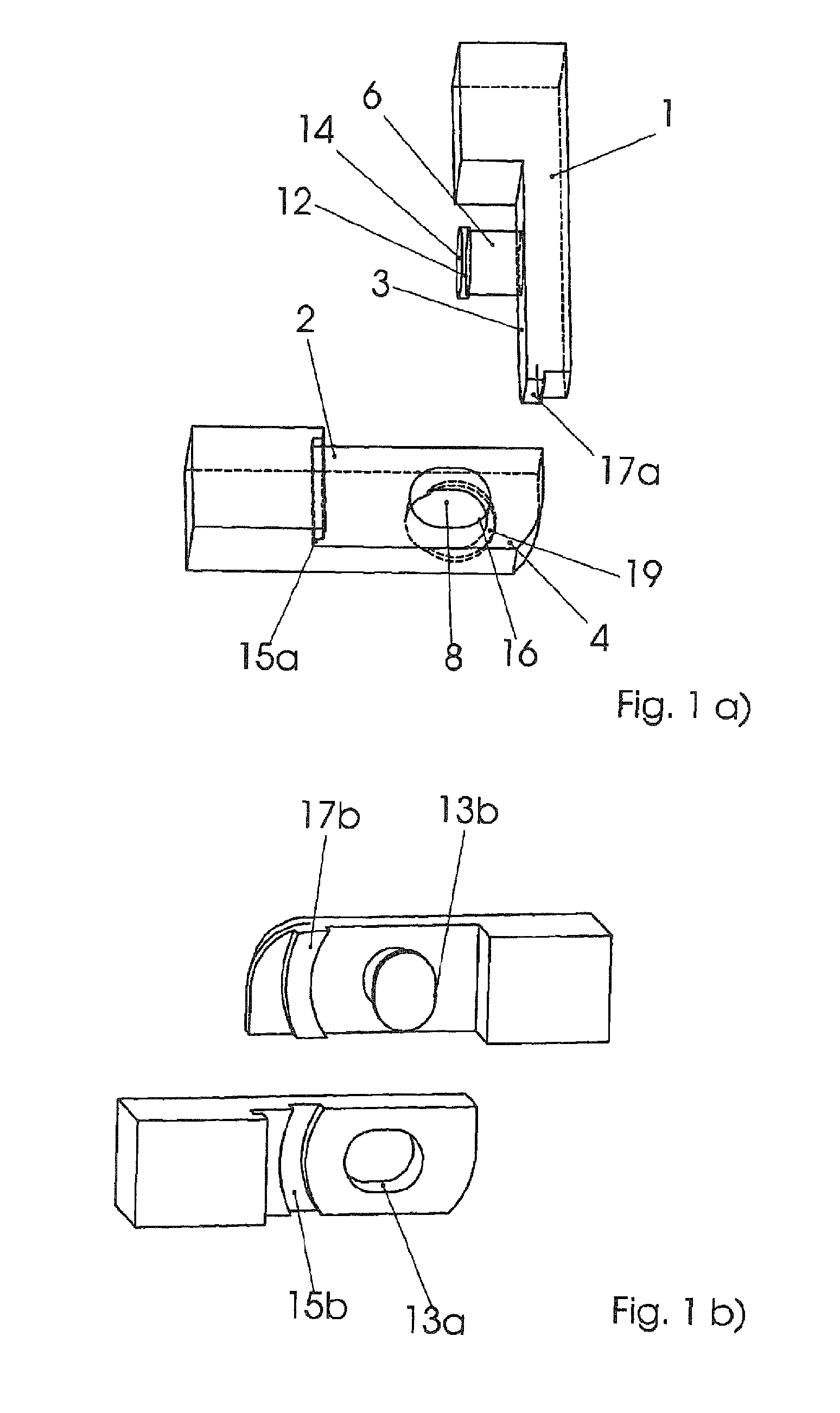
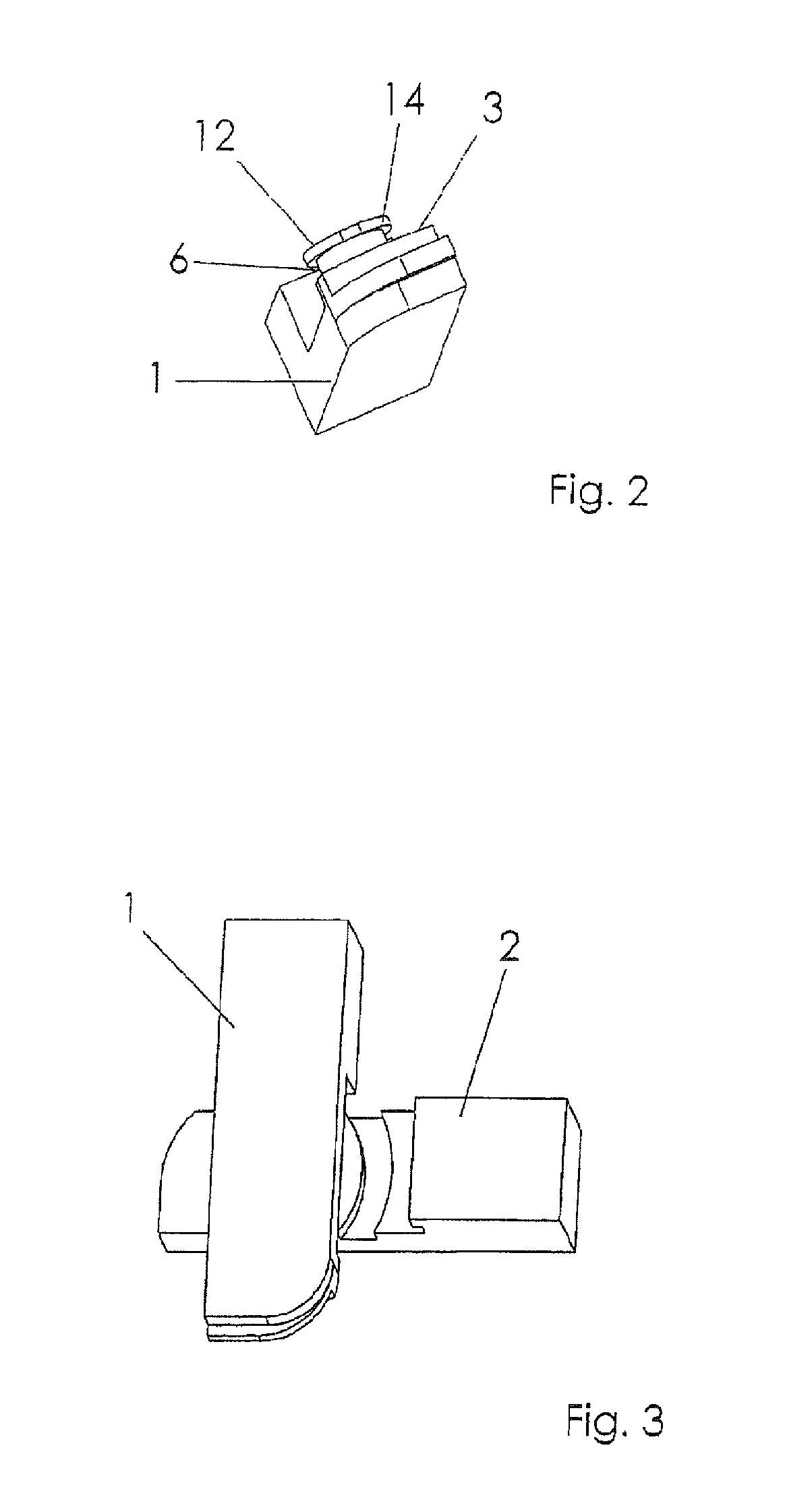
[0032]The rod coupling according to FIG. 1 includes a first coupling member 1 and a second coupling member 2. Each of the coupling members has coupling area 3 or 4, wherein the coupling area 3 has a pin 6 that is not completely cylindrical and that corresponds to a recess 8 of the coupling area 4. At its ends, the pin 6 has two shoulders 12, 14 that are vertically oriented in relation to the plane of the rod assembly axis. The recess 8 is non-cylindrically shaped (see section 13b) and has a groove 16 that corresponds to the shoulders 12, 14 and that is horizontally oriented in relation to the rod assembly axis.

[0033]The orientation of the shoulders 12, 14 and the flat areas 13a and 13b as well as the groove 16 effectuate that the rod segments must be arranged at a right angle in relation to each other when they are being connected so as to align the shoulder 12 with the groove 16 (cf. position in FIG. 3). If the flat areas 13a and 13b align (plug-in angle), the pin 6 can be inserted...


PUM


Abstract

The invention relates to a rod coupling for rod segments for use in horizontal earth boring, wherein the ends of the rod segments can be interconnected and are fixed by means of a cross pin.

Description

CROSS-REFERENCES TO RELATED APPLICATIONS[0001]This application is the U.S. National Stage of International Application No. PCT / EP2008 / 002714, filed Apr. 4, 2008, which designated the United States and has been published as International Publication No. WO 2008 / 122423 and which claims the priority of German Patent Application, Serial No. 10 2007 016 822.7, filed Apr. 5, 2007, pursuant to 35 U.S.C. 119(a)-(d).[0002]The invention relates to a rod coupling as it is used for connecting rod assemblies for underground horizontal boring and trench-less installation or replacing of pipelines (horizontal boring hereinbelow).[0003]In horizontal boring, individual rod assemblies are strung together, connected with each other and moved through the ground by means of a push, pull, or rotary drive. In the case of longer borings, the rod assembly includes multiple rod segments which are, in accordance with the progress of the boring, connected with or separated from each other, one at a time. The i...

Claims


Application Information

Patent Timeline
Patent Type & Authority Patents(United States)
IPC IPC(8): E21B17/02
CPCE21B17/046Y10T403/7015Y10T403/553F16B21/04
Inventor PUTTMANN, FRANZ-JOSEF
Owner TRACTO TECHN
Why Eureka
Try Eureka