
Device for sectioning an electrical circuit and a system for distributing electrical energy including the sectioning device

a technology of electrical circuit and sectioning device, which is applied in the direction of electrical apparatus, electrical devices with unconnected briding contacts, electromagnetic relay details, etc., can solve the problems of increasing the risk of electrocution of the sectioning device upon contact with the main sectioning terminal, and achieve the effect of reducing the risk of electrocution

Active Publication Date: 2012-11-27
ALSTOM TRANSPORT TECH SAS
View PDF11 Cites 2 Cited by
  • Summary
  • Abstract
  • Description
  • Claims
  • Application Information

AI Technical Summary

Benefits of technology

The invention provides a device for safely sectioning electrical circuits, reducing the risk of electrocution. The device includes two secondary sectioning terminals and a second sectioning member that is movable between open and closed positions. The second sectioning member is mechanically coupled to the first sectioning member and its commutation is predetermined. The device also includes an automatic control means and a manual control member for controlling the first sectioning member. The device can be used in a system for supplying electrical power to at least two electrically conductive rails. The system includes an auxiliary terminal connected to electrical earth and a grounding circuit for each conductive rail. The sectioning of the electrical power supply circuit is achieved by commutation of the first sectioning member.

Problems solved by technology

However, such a sectioning device involves risks of electrocution upon contact with the main sectioning terminals when the circuit is open, that is to say, when the first sectioning member is in the open position.
Those risks are even more pronounced because the resetting of the sectioning device is manual.

Method used


Image

  • Device for sectioning an electrical circuit and a system for distributing electrical energy including the sectioning device
  • Device for sectioning an electrical circuit and a system for distributing electrical energy including the sectioning device
  • Device for sectioning an electrical circuit and a system for distributing electrical energy including the sectioning device

Examples


Embodiment Construction

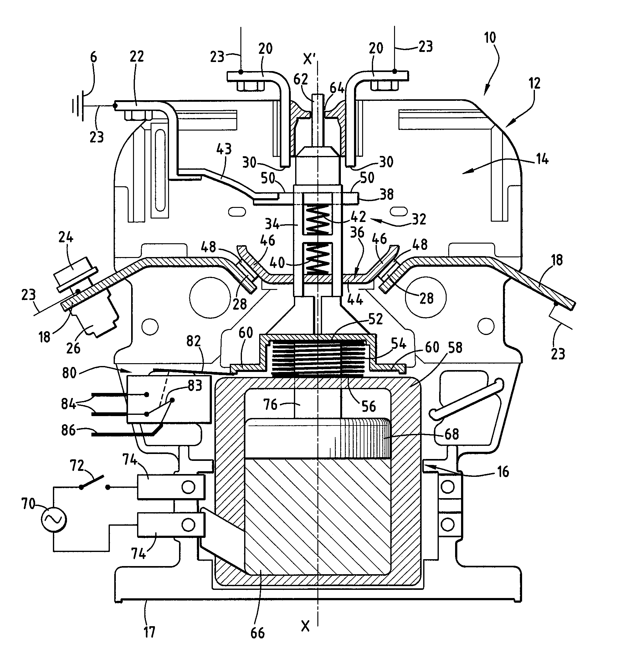
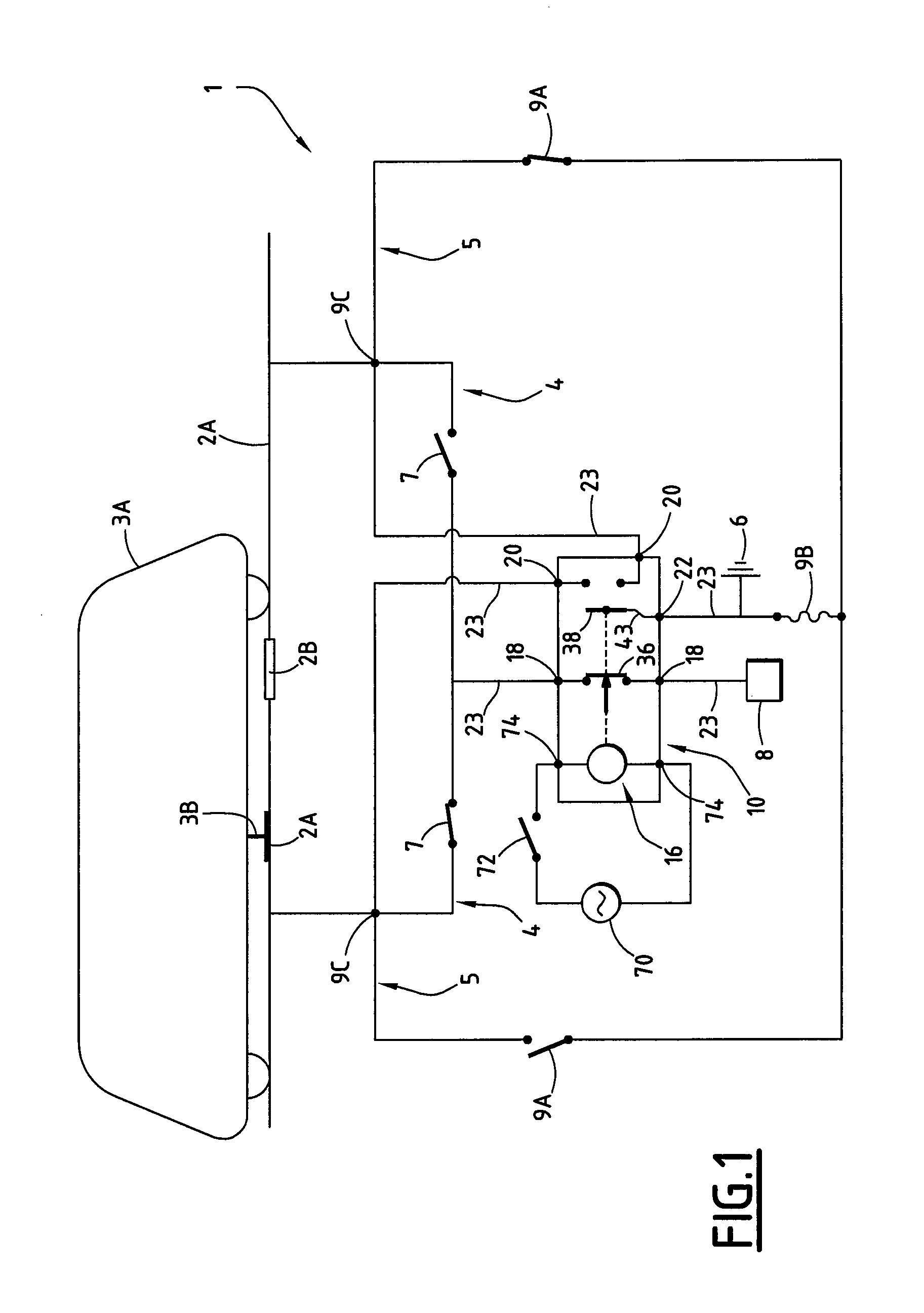
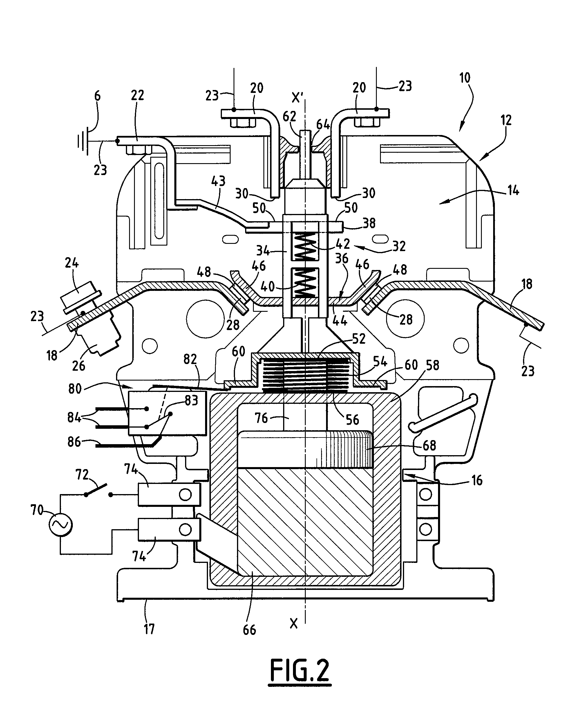
[0023]FIG. 1 illustrates a system 1 for supplying electrical power to two electrically conductive rails 2A which are connected to each other by an insulating portion 2B. The electrically conductive rails 2A are capable of providing electrical current to a rail vehicle 3A by means of an electrically conductive runner 3B. The supply system 1 comprises a circuit 4 for supplying electrical power to a conductive rail 2A and a circuit 5 for connecting to electrical ground 6 the other conductive rail 2A or the two conductive rails 2A when no conductive rail 2A is supplied with electrical power by the supply circuit 4.

[0024]The supply circuit 4 comprises a first switch 7 for each conductive rail 2A and a current source 8. The grounding circuit 5 comprises a second switch 9A for each conductive rail 2A and a fuse 9B for connection to electrical ground 6. The supply circuit 4 and the grounding circuit 5 comprise common connection points 9C.

[0025]The supply system 1 comprises a device 10 for s...


PUM


Abstract

A device for sectioning an electrical circuit is provided. The device includes a housing having two main sectioning terminals and, in the housing, a first member for sectioning a first electrical connection between the two main sectioning terminals, an automatic control, under the action of an electrical signal, of the first sectioning member from the closed position to the open position thereof, and a manual control member for resetting the first sectioning member from the open position to the closed position thereof. The device also includes, in the housing, two secondary sectioning terminals and a second sectioning member movable between a position for opening and a position for closing a second electrical connection between the two secondary sectioning terminals, the second sectioning member being coupled to the first sectioning member, commutation of the first sectioning member bringing about commutation of the second sectioning member.

Description

[0001]This claims priority to FR 08 58080 filed on Nov. 28, 2008 and hereby incorporated by reference herein.[0002]The present invention relates to a device for sectioning an electrical circuit.[0003]The invention also relates to a system for supplying electrical power to at least one electrically conductive rail which is capable of supplying electrical current to a rail vehicle.BACKGROUND OF THE INVENTION[0004]Devices for sectioning an electrical circuit are used in order to open or close a connection of that electrical circuit, and allow a minimum physical distance to be ensured between the first sectioning member and the corresponding sectioning terminals when the circuit is open. Sectioning devices are used, for example, in units for distributing electrical energy for rail vehicles.[0005]Patent Application EPO479694A1 discloses a sectioning device. The first sectioning member is a movable bar which is composed of insulating material and which is provided with electrical contacts...

Claims


Application Information

Patent Timeline
Patent Type & Authority Patents(United States)
IPC IPC(8): H01H13/04
CPCH01H31/003H01H50/546H01H51/01H01H9/0066H01H31/24
Inventor DURAND, JEAN-MARCDELTEIL, JEREMY
Owner ALSTOM TRANSPORT TECH SAS
Learn More