
Method and apparatus for optical fiber coating removal

a coating and optical fiber technology, applied in the direction of chemistry apparatus and processes, instruments, optical elements, etc., can solve the problems of optical fiber surface scoring or scratching, glass optical fibers with very small diameters, and easy external influences, etc., to achieve simple and inexpensive effects

Active Publication Date: 2012-11-27
CORNING INC
View PDF12 Cites 5 Cited by
  • Summary
  • Abstract
  • Description
  • Claims
  • Application Information

AI Technical Summary

Benefits of technology

[0017]It is an advantage of the present invention that it provides a clean, simple and inexpensive way for removing coating from a coated optical fiber. Another advantage is that the disclosed system is capable of supporting and guiding the optical fiber under the stream of hot gas directed onto that portion of the coating material which is to be removed.

Problems solved by technology

Glass optical fibers have very small diameters and are susceptible to external influences such as mechanical stress and environmental conditions.
Alternatively, a heater within the coating removal apparatus can also cause softening and swelling of the coating.
Mechanical strippers can cause scoring or scratching of the fiber surface.
Some stripping methods do not result in a clean demarcation between the stripped coating and the coating remaining on the fiber.
If the stripping process results in a ragged or uneven coating termination, the resultant stripped fiber may not be useful for its intended purpose.
Mechanical stripping can also contaminate the fiber surface, thus requiring a subsequent cleaning step to remove particulates.
The wiping step can cause more damage to the fiber than the mechanical stripping step.
Chemical stripping processes can be disadvantages in that they are difficult to control, and they may leave contaminants or residual coating on the fiber surface.
Chemical stripping can also be disadvantages in that it utilizes dangerous caustic chemicals that need to be handled and disposed of.

Method used


Image

  • Method and apparatus for optical fiber coating removal
  • Method and apparatus for optical fiber coating removal
  • Method and apparatus for optical fiber coating removal

Examples


example 1

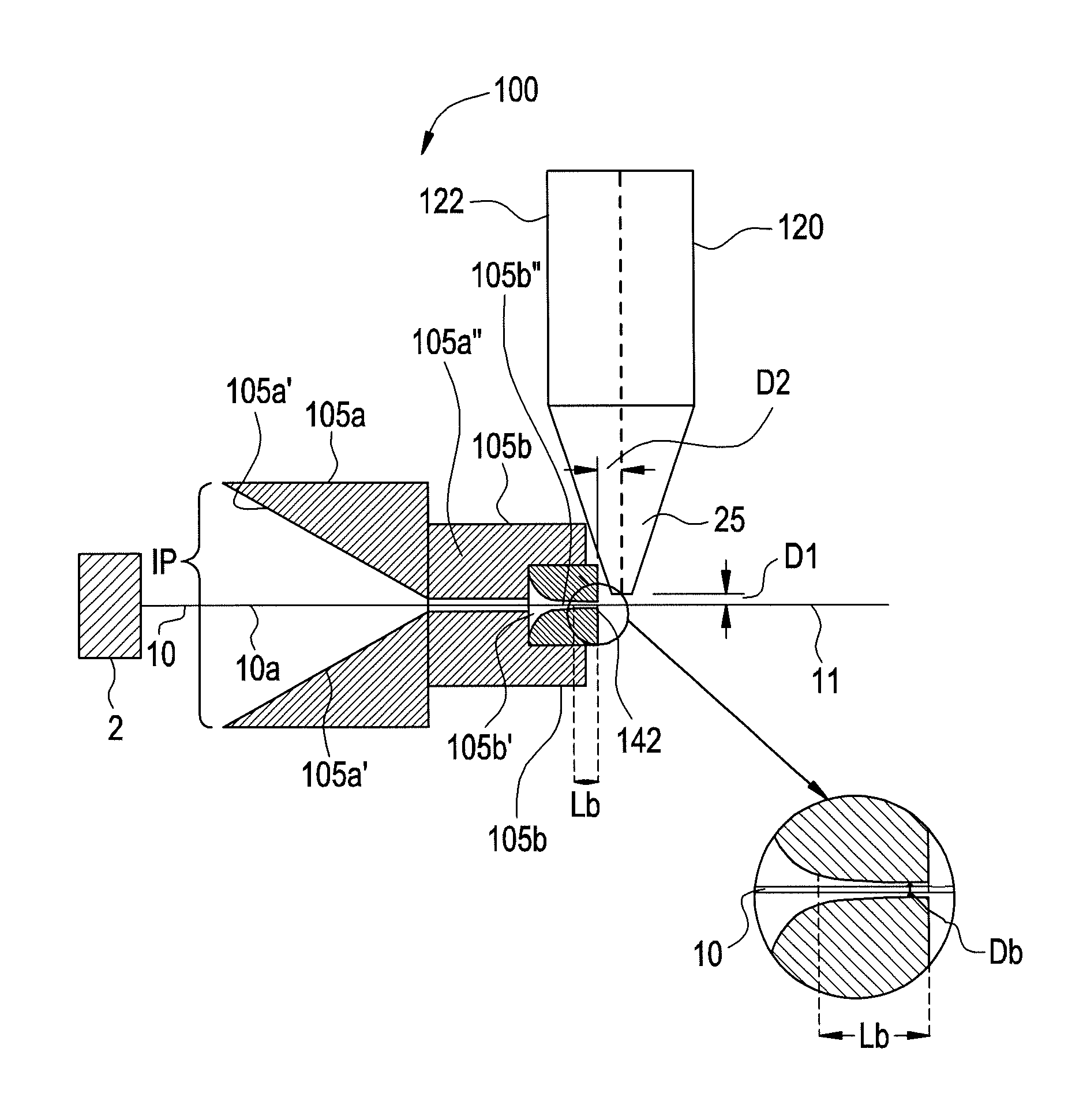
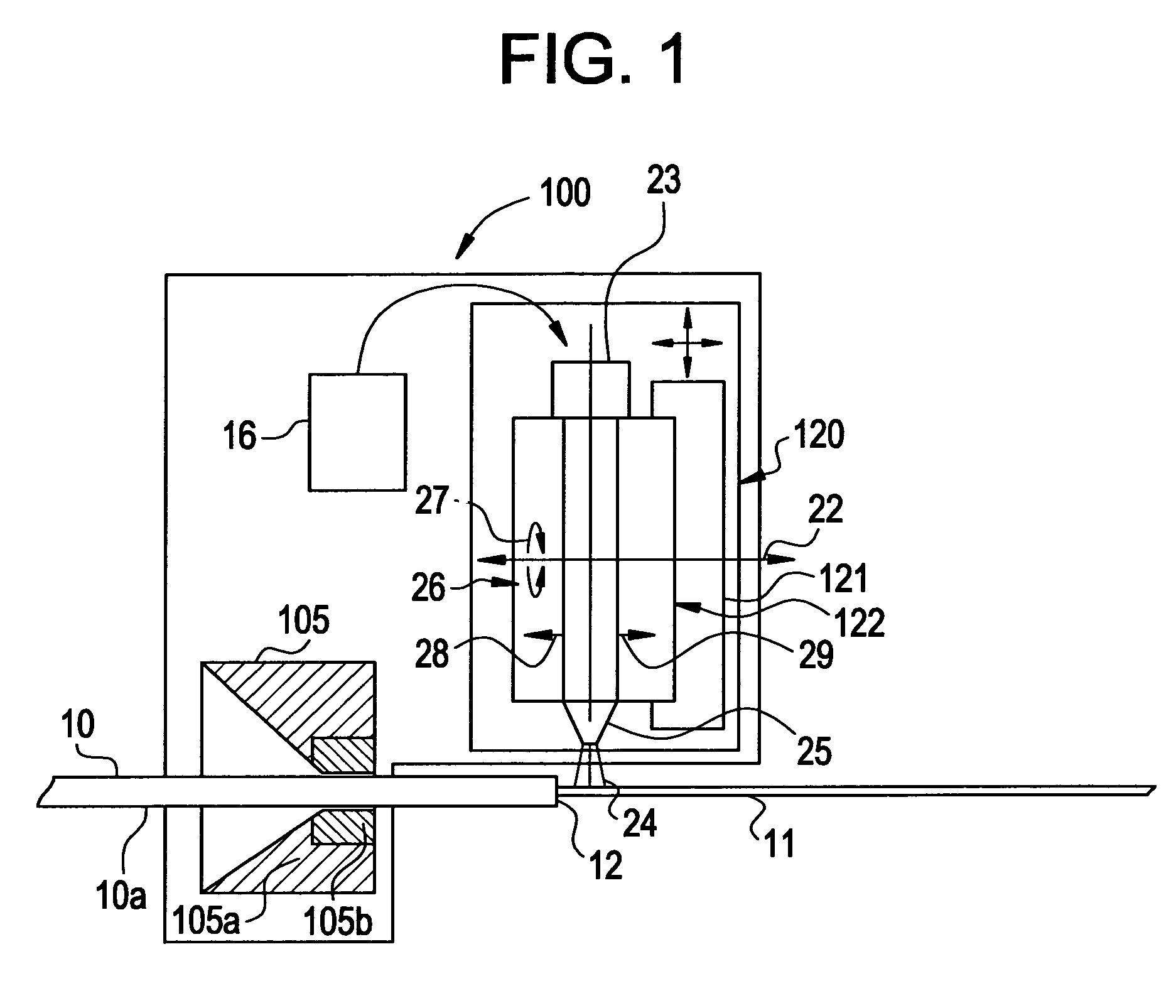
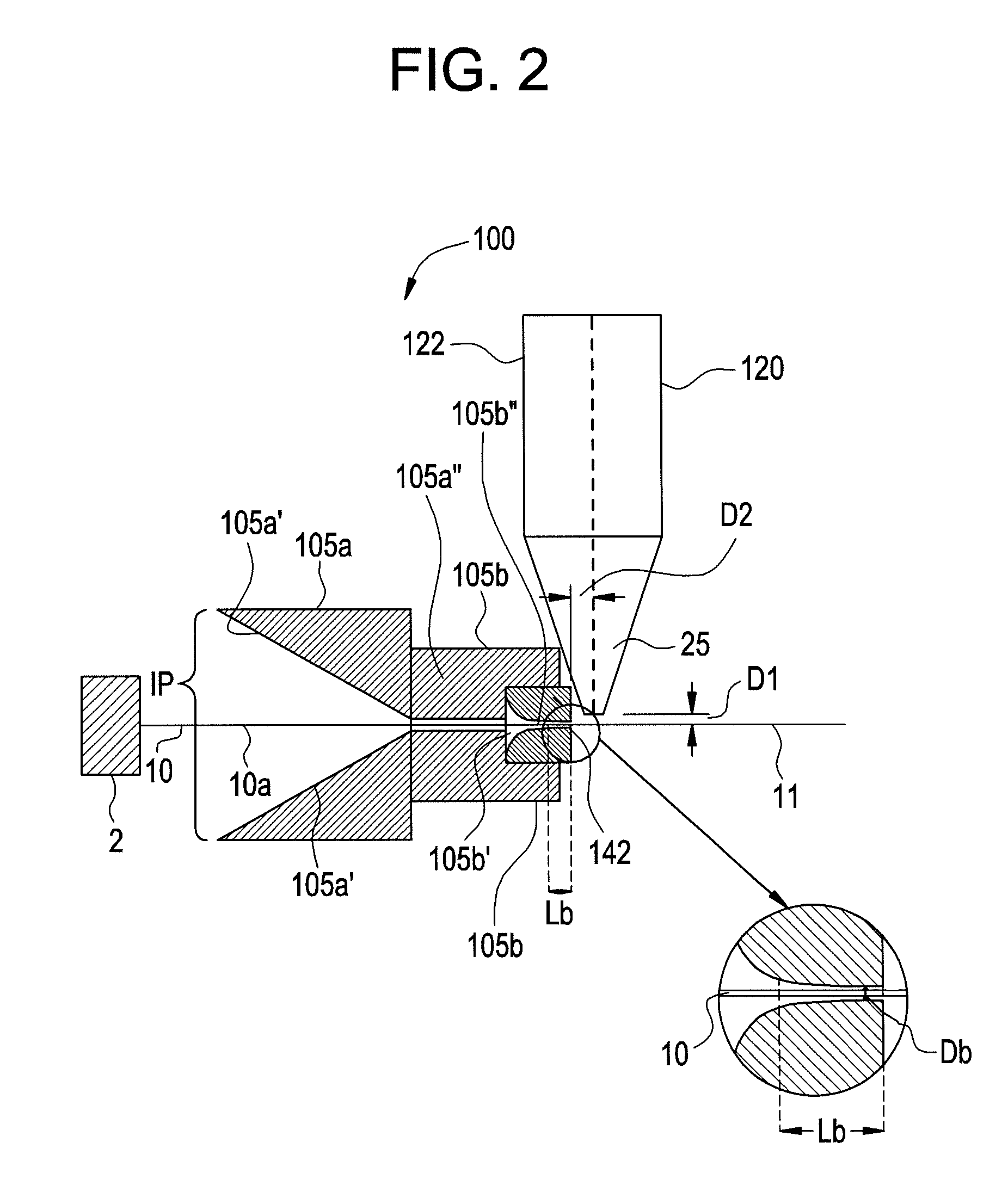
[0040]FIG. 2 illustrates one method for collecting a free end 10a of the coated optical fiber 10 and guiding and supporting the coated optical fiber 10; presenting it to the hot gas stripper 120 used in an automated coating removal system. In this embodiment the hot gas stripper 120 includes integral heater apparatus nozzle. The fiber collection and support device 105 for guiding and supporting the free end 10a of the fiber 10 is shown in cross-section for discussion purposes, and the fiber 10 is shown in its full extended position relative to the hot gas nozzle 25. The relative position of the fiber collection and support device 105 and the hot gas stripper 120 are maintained such that dimensions D1 and D2 are held constant. The coated fiber 10, the fiber guide collection and support device 105 and nozzle 25 (formed integrally with the heater of the hot gas stripper 120) may move independently of each other. The fiber collection and support device 105 comprises a coarse conical fib...

example 2

[0044]The fiber collection and stripping system 100 of this embodiment also utilizes a hot gas stripper 100 and fiber collection and support device 105. The hot gas stripper 100 is similar to the one illustrated in FIGS. 1 and 2. Preferably, the fiber collection and support device 105 is moved towards fiber 10 to collect the free end 10a of the coated optical fiber.

[0045]As in the previously described embodiment, the fiber collection and support device 105 (See FIG. 4b) for collecting, guiding, and supporting a free end of the coated optical fiber 10 during stripping includes a coarse conical collector 105a and the fine fiber centering collector 105b. The coarse conical collector 105a includes a guide funnel 105a′ and a coarse guide tube 105a″. The fine fiber centering collector 105b includes a fine guide tube 105b″. However, with reference to FIGS. 4a and 4b the fiber collection and support device 105 includes two mating sides 16 and 17 that are movable with respect to one another....

example 3

[0047]FIG. 5 illustrates a fiber collection and stripping system 100 similar to that shown in FIG. 2. It also maintains separation between fiber collection and support device 105 and hot gas stream nozzle 25, thus minimizing heat transfer to the fiber collection and the support device 105. Features such as conical fiber guide funnel 105a′, coarse guide tube 105a″ and fine fiber centering collector 105b (support die) serve similar functions as described in example 2 illustrated in FIG. 2. In the present exemplary embodiment, the heater apparatus 122 is similar to that of Convectronics Models 001-10005 and 001-10007, but has an open end which serves as a nuzzle 25 (versus the integral nozzle shown in FIG. 2). This hot gas nozzle 25 is separate from the heater apparatus 122 and made of an insulating material 132 capable of handling a minimum temperature of 1600° F. The insulated heater 122 and nozzle 25 produce a larger effective hot gas stripping zone. Separation of the nozzle and hea...


PUM

PropertyMeasurementUnit
temperatureaaaaaaaaaa
gas flow rateaaaaaaaaaa
speedaaaaaaaaaa

Abstract

A method for removing a protective coating material from a portion of an optical fiber including a glass optical fiber having an outer surface surrounded by said protective coating material, said method comprising the steps of: (i) providing a fiber collection and support device having: (a) a coarse conical fiber collector having an input port and (b) a fine fiber centering collector including a fiber tube having an output port, said input port is larger then said output port; (ii) providing the fiber threaded through the course conical collector into the fiber collection tube of the fine fiber centering collector; (iii) contacting the fiber, as it exits from the output port of the fiber collection tube of the fiber collection and support device, with a stream of hot gas; and (iv) directing a stream of a hot gas onto the protective coating material that is to be removed.

Description

[0001]This application claims the benefit of U.S. Provisional Application No. 60 / 861,921, filed Nov. 30, 2006, entitled “METHOD AND APPARATUS FOR OPTICAL FIBER COATING REMOVAL”.BACKGROUND OF THE INVENTION[0002]1. Field of the Invention[0003]The present invention relates generally to a method and apparatus for removing protective coating material from an optical fiber with a stream of hot gas. The hot gas softens the coating and blows it from the fiber.[0004]2. Technical Background[0005]Glass optical fibers have very small diameters and are susceptible to external influences such as mechanical stress and environmental conditions. To protect the fiber from such influences, it is provided with one or more coatings of protective material.[0006]It is important that the stripped portions of the fibers do not become weakened during the stripping process since weakened fibers can fail during subsequent handling. Therefore, the coating stripping process should not inordinately reduce fiber s...

Claims


Application Information

Patent Timeline
Patent Type & Authority Patents(United States)
IPC IPC(8): B32B38/10
CPCG02B6/245Y10T156/1153Y10T156/1939Y10T156/1137Y10T156/1972Y10T156/1168Y10T156/1911
Inventor DUNWOODY, STEVEN AKINPALMER, OSCAR
Owner CORNING INC
Learn More