
Event-driven fault diagnosis framework for automotive systems

a technology of automotive system and fault diagnosis, applied in the field of system and method of diagnosing fault conditions in vehicles, can solve problems such as troubleshooting particularly difficult, failures and faults affecting the operation of vehicles, and difficulty in diagnosing the true root cause of problems based on a dtc value alone, and achieve the effect of remaining useful li

Active Publication Date: 2012-10-30
GM GLOBAL TECH OPERATIONS LLC
View PDF9 Cites 21 Cited by
  • Summary
  • Abstract
  • Description
  • Claims
  • Application Information

AI Technical Summary

Benefits of technology

This approach improves fault diagnosis accuracy, reduces missed diagnoses, and enables more effective system design improvements by providing clear insights into failure modes and their causes, enhancing customer satisfaction and reducing warranty costs.

Problems solved by technology

As with anything, these types of devices and algorithms are susceptible to errors, failures and faults that affect the operation of the vehicle.
When such errors and faults occur, often the affected device or component will issue a fault code, such as a diagnostic trouble code (DTC), that is received by one or more system controller identifying the fault, or some ancillary fault with an integrated component.
However, given the complexity of vehicle systems, many DTCs and other signals could be triggered for many different reasons, which could make trouble-shooting particularly difficult.
This often makes it difficult to diagnose the true root cause of a problem based on a DTC value alone.
This can result in the inability to find or repeat a problem when the vehicle is being serviced, which leads to customer dissatisfaction, increased future warranty costs, and missed opportunities to improve system designs based on real-world failure modes.

Method used


Image

  • Event-driven fault diagnosis framework for automotive systems
  • Event-driven fault diagnosis framework for automotive systems
  • Event-driven fault diagnosis framework for automotive systems

Examples


Embodiment Construction

[0014]The following discussion of the embodiments of the invention directed to an event-driven fault diagnosis framework for automotive systems is merely exemplary in nature, and is in no way intended to limit the invention or its applications or uses. For example, the present invention has particular application for vehicle fault diagnosis. However, the method of the invention will have other applications for other industries, such as fault diagnosis in the aerospace, heavy equipment, and other transportation industries.

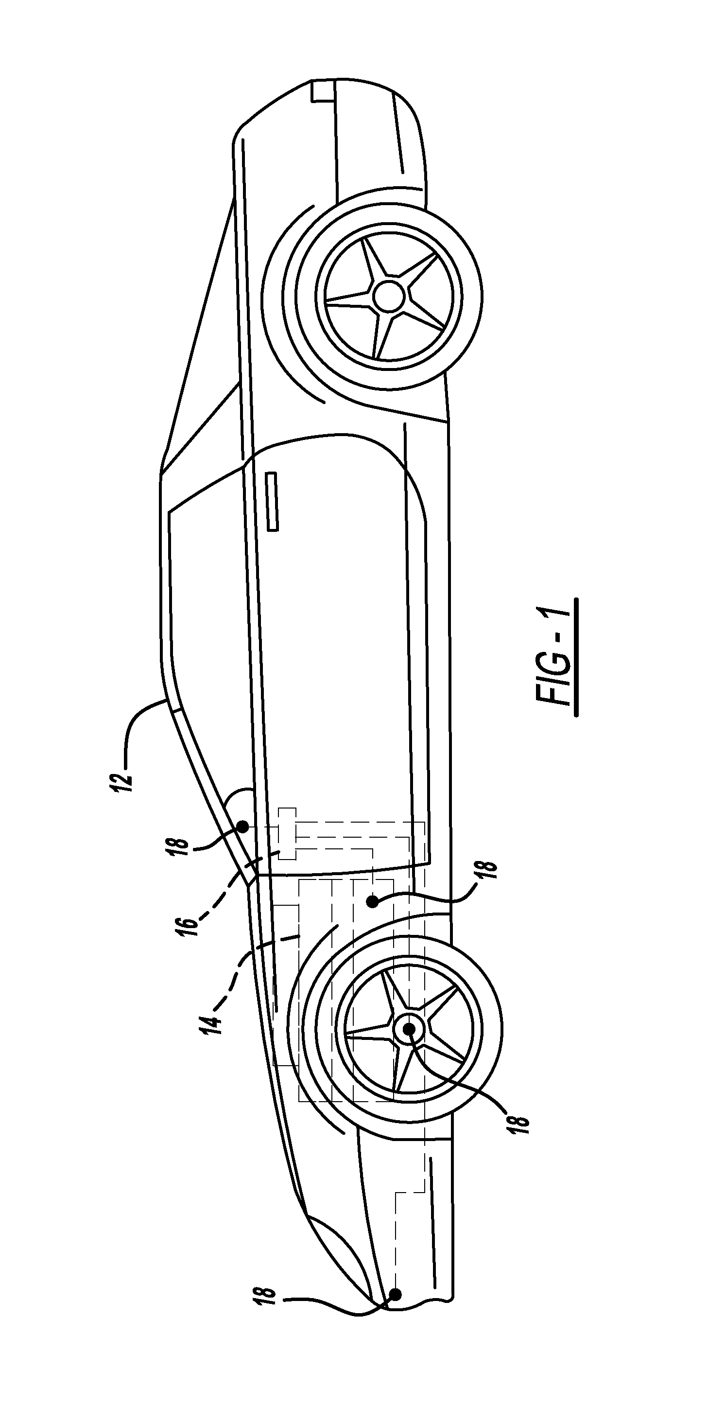
[0015]FIG. 1 is a diagram of a vehicle 12 with onboard equipment needed for capturing fault-related data. The vehicle 12 includes an engine 14, and numerous other systems and sub-systems, such as suspension, steering, transmission and driveline, thermal management, entertainment, and security systems. Each of these systems is typically comprised of many sub-systems and components, which must be in good working condition in order for the parent system to function pro...


PUM


Abstract

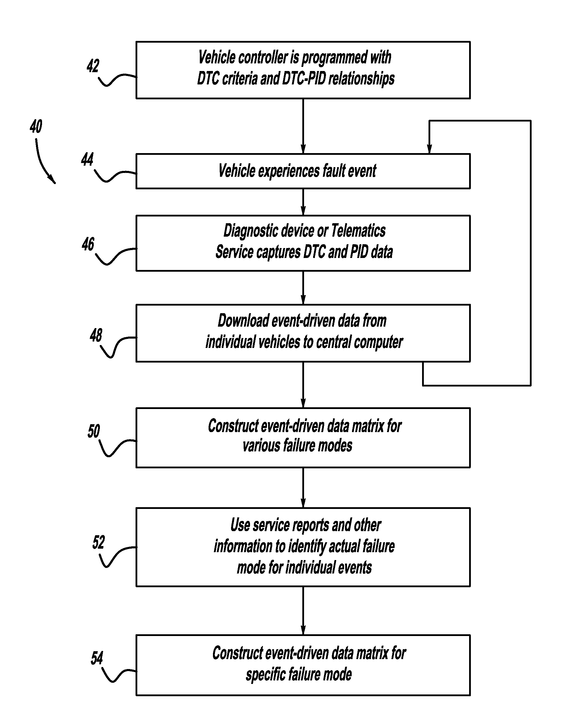
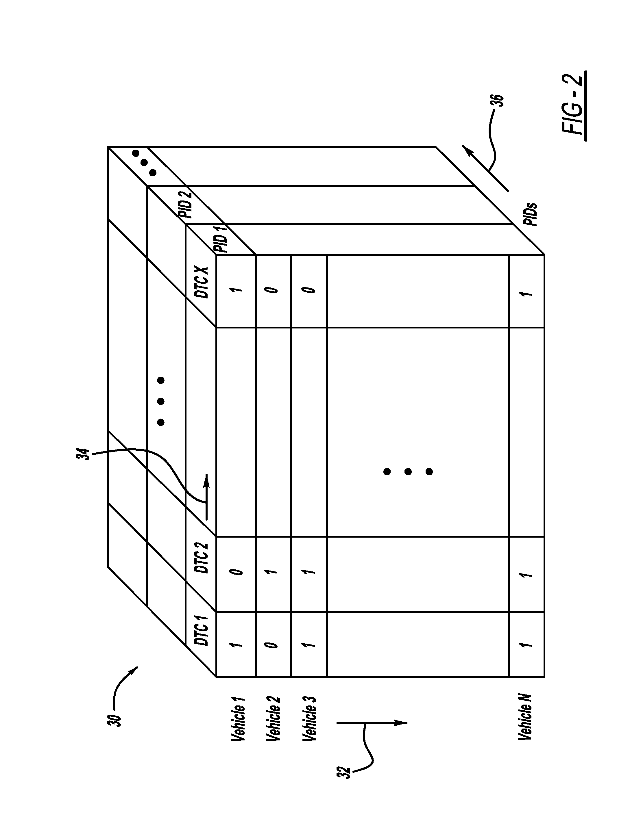
Systems and methods for capturing and analyzing significant parameter data from vehicle systems whenever a diagnostic trouble code (DTC) is triggered. A multi-dimensional matrix is constructed, with vehicles, DTCs, and parameter data comprising three dimensions of the matrix. The data matrix is populated with DTC and parameter data from many different vehicles, either when vehicles are taken to a dealer for service, or via wireless data download. Time can be added as a fourth dimension of the matrix, providing an indication of whether a particular system or component is temporally degrading. When sufficient data is accumulated, the data matrix is pre-processed, features are extracted from the data, and the features are classified, using a variety of mathematical techniques. Trained classifiers are then used to diagnose the root cause of any particular fault signal, and also to provide a prognosis of system health and remaining useful life.

Description

BACKGROUND OF THE INVENTION[0001]1. Field of the Invention[0002]This invention relates generally to a system and method for diagnosing fault conditions in a vehicle and, more particularly, to a system and method for capturing operating parameter data whenever a diagnostic trouble code (DTC) is triggered in a vehicle, and applying mathematical models to both the parameter data and the DTC data to diagnose the reason for the fault condition.[0003]2. Discussion of the Related Art[0004]Modern vehicles are complex electrical and mechanical systems that employ many components, devices, modules, sub-systems, etc. that pass operating information between and among each other using sophisticated algorithms and data buses. As with anything, these types of devices and algorithms are susceptible to errors, failures and faults that affect the operation of the vehicle. When such errors and faults occur, often the affected device or component will issue a fault code, such as a diagnostic trouble co...

Claims


Application Information

Patent Timeline
Patent Type & Authority Patents(United States)
IPC IPC(8): G01M17/00G06F7/00G06F19/00
CPCG07C5/0808
Inventor SINGH, SATNAMCHOUGULE, RAHULBANDYOPADHYAY, PULAK
Owner GM GLOBAL TECH OPERATIONS LLC
Learn More