
Compact optical system and packaging for head mounted display

a technology of optical systems and head mounted displays, applied in the field of compact optical systems, can solve the problems of physical design that fails to adequately take into account such important human factors, the display is too heavy for comfortable use, and the optics system is relatively large within the mounting structure, so as to achieve greater convenience and acceptability

Active Publication Date: 2012-10-16
IBM CORP
View PDF25 Cites 42 Cited by
  • Summary
  • Abstract
  • Description
  • Claims
  • Application Information

AI Technical Summary

Benefits of technology

The present invention provides an optical system design for use in display devices such as head mounted virtual image displays. The design overcomes defects of conventional designs, such as size and weight, obstructed view, etc. The optical system is compact, lightweight, and offers a clear see-through capability. It can be used with eye or safety glasses and is designed to enhance user acceptability. The optical system can be combined with a computer-based device to form a portable computer system. The technical effects of the invention include improved image quality, reduced size and weight, and improved user experience.

Problems solved by technology

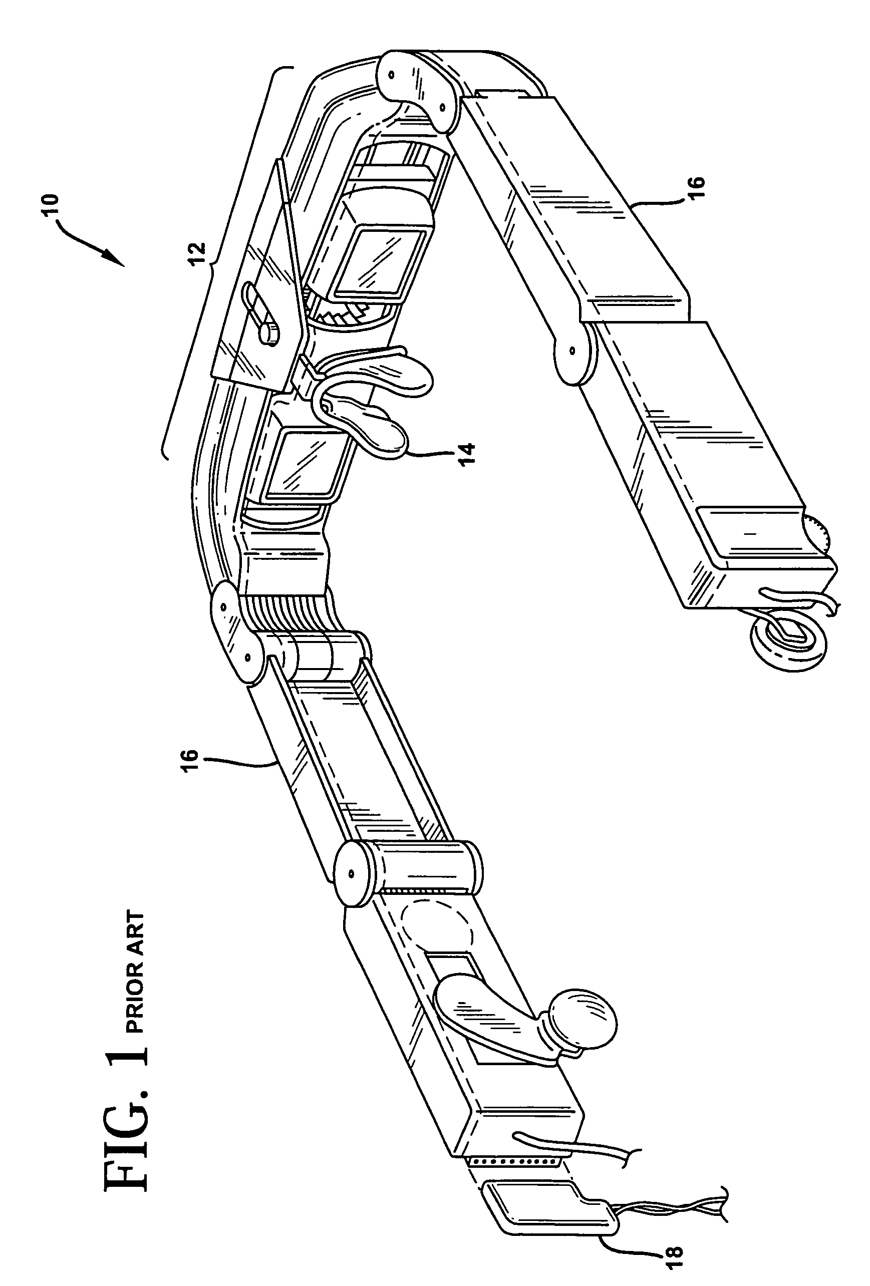
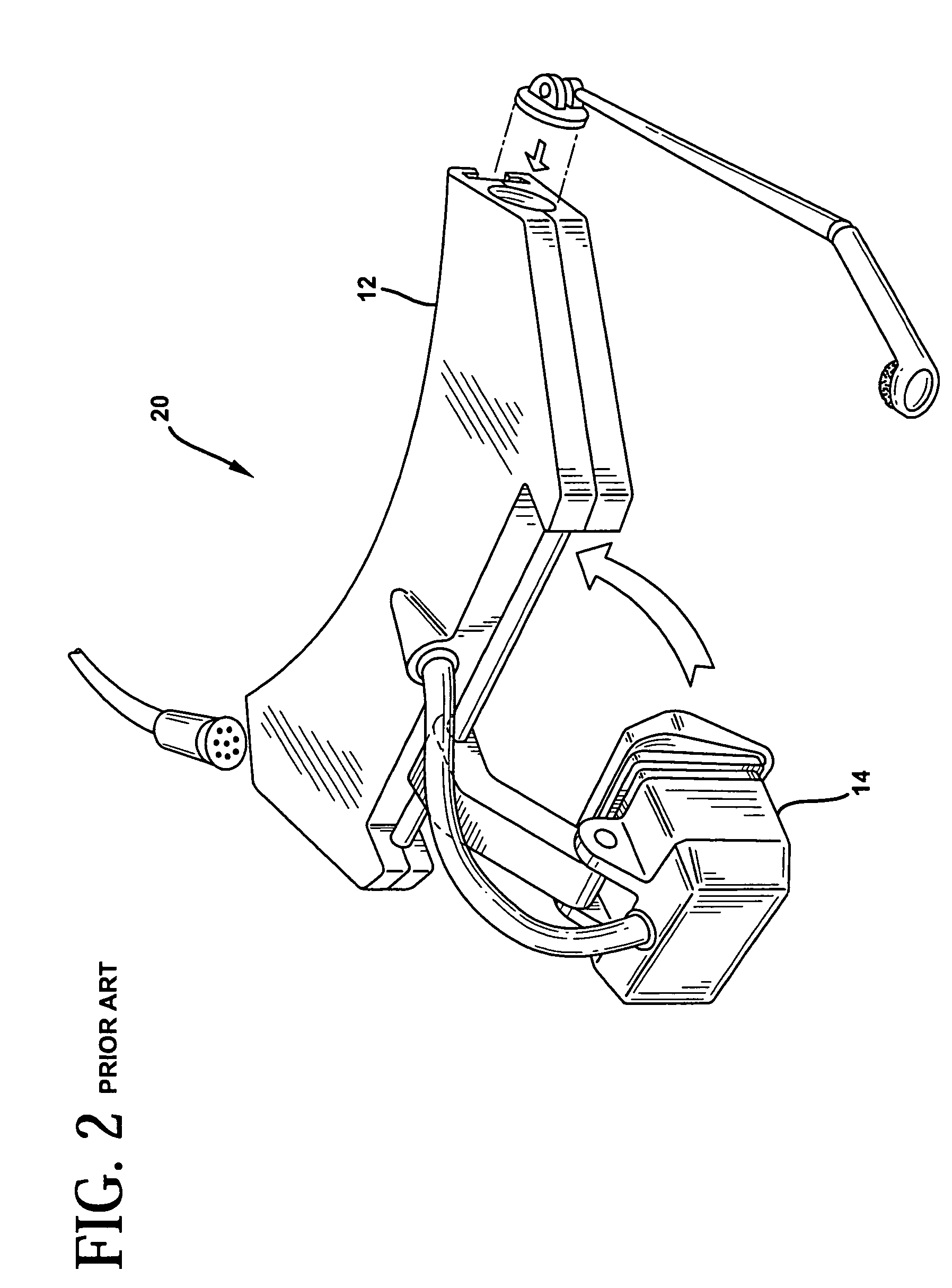
For example, such displays have suffered from being too heavy for comfortable use, as well as too large so as to be obtrusive, distracting, and even disorienting.
These defects stem from, among other things, the incorporation of relatively large optics systems within the mounting structures, as well as physical designs which fail to adequately take into account such important human factors as size, shape, weight, etc.
It is known that such a unit is cumbersome and permits the wearer to see substantially nothing other than the display screen.
That is, the user is unable to view his immediate environment.
This design is also known to be cumbersome and likely to obstruct the users surrounding view.
However, all of the examples given suffer from one or more of the above-mentioned design deficiencies.
As a result, such deficiencies have seriously hindered the general acceptance of such devices.

Method used


Image

  • Compact optical system and packaging for head mounted display
  • Compact optical system and packaging for head mounted display
  • Compact optical system and packaging for head mounted display

Examples


Embodiment Construction

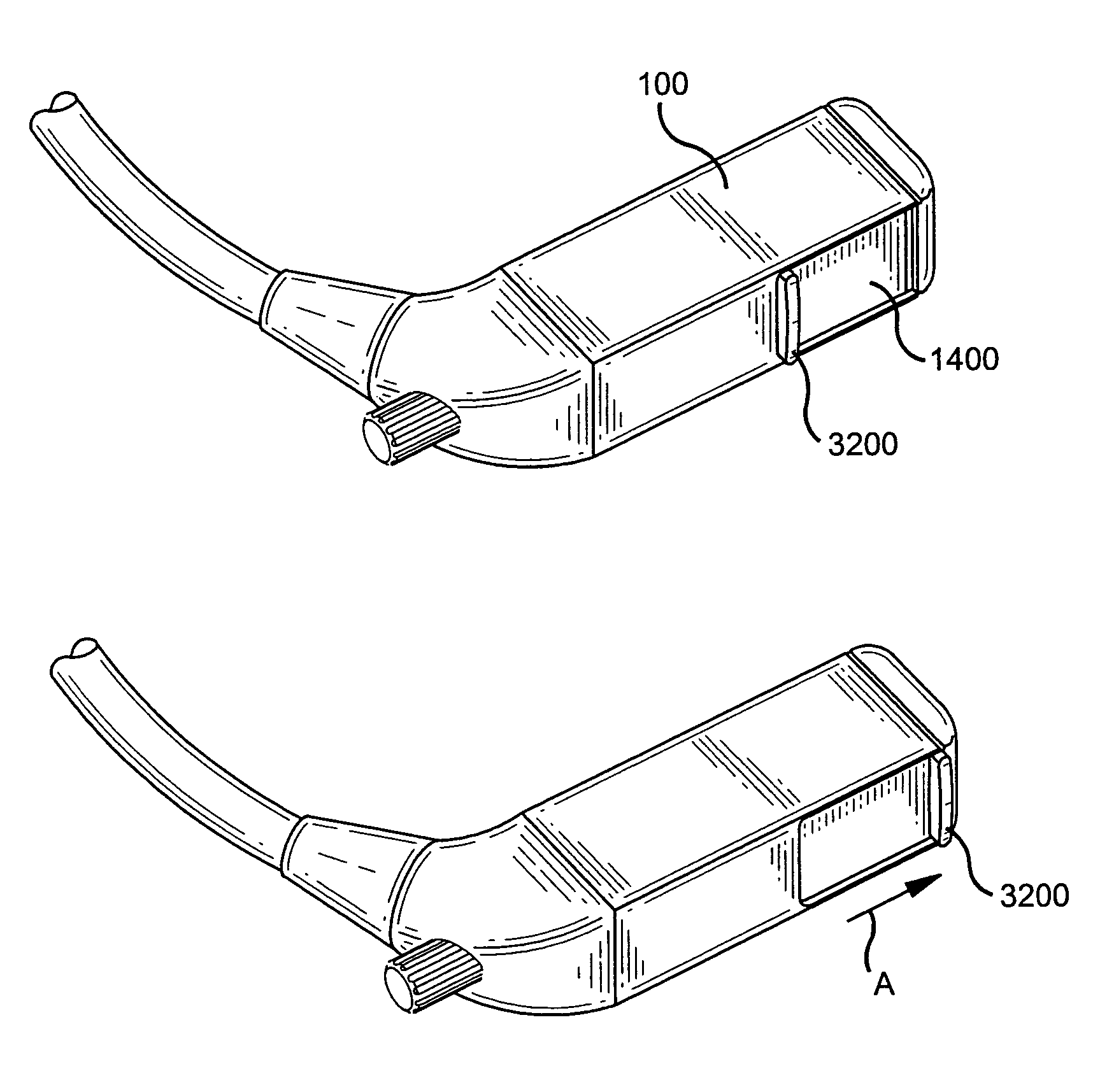
[0028]An optical system design of the present invention will be explained below in the context of a head mounted virtual image display unit and wearable computer. However, it is to be understood that the present invention is not limited to this or any particular display application. Rather, the invention is more generally applicable to any suitable display application in which it is desirable to utilize a compact optical system for displaying images which may be incorporated into a device used in the application. Such devices may be, for example, personal devices such as wearable personal computers, head mounted displays, portable telephones and the like.

[0029]Referring initially to FIGS. 3A and 3B, a head mounted virtual display unit 10 and computer-based device 20 according to one embodiment of the present invention are shown. A cable 30 is provided for electrically coupling the computer-based device 20 with the head mounted virtual display unit 10. FIGS. 3A and 3B illustrate the ...


PUM


Abstract

A head mounted virtual image display unit is provided which is compact in size and weight, and incorporates a high performance optical system offering a clear see-through capability. A sliding light shield may be incorporated for those instances when see-through capability is not desired. A focus adjustment may be incorporated to permit the focusing of the image, for example, at a distance of approximately 18 inches to infinity. An adjustable headband may be incorporated that adapts to fit the users head. A flexible boom structure may be incorporated to facilitate fine positional adjustment of the optical assembly. A slider and ball joint mechanism may also be incorporated to facilitate positional adjustment of the optical assembly. A built-in microphone may be incorporated to enable speech input by the user. The head mounted virtual image display unit may be used comfortably in conjunction with eye or safety glasses, and provides a useful image to the user without blocking his view of the surrounding environment. The unit is designed to have a pleasing appearance so as to greatly enhance user acceptability.

Description

CROSS REFERENCE TO RELATED APPLICATION[0001]This application is a divisional of U.S. application Ser. No. 09 / 626,749, filed Jul. 27, 2000, now U.S. Pat. No. 6,747,611, the disclosure of which is incorporated by reference herein.FIELD OF THE INVENTION[0002]The present invention relates generally to compact optical systems and, more particularly, to compact optical systems for use in display devices, for example, personal devices such as wearable personal computer systems, head mounted displays, portable telephones and the like.BACKGROUND OF THE INVENTION[0003]Virtual image displays combine magnifying optics with a small image panel to provide the viewer with a virtual image capable of displaying large amounts of information. Such displays have found application in so called head mounted displays and are used in conjunction with a computer-based device for a variety of applications. As is known, the computer-based device includes processing and display driver circuitry for generating ...

Claims


Application Information

Patent Timeline
Patent Type & Authority Patents(United States)
IPC IPC(8): G09G5/00G02B5/04G02B5/10G02B5/30G02B17/08G02B27/00G02B27/01G02B27/02H04N5/64
CPCG02B27/0172G02B27/0176G02B5/30G02B2027/0132G02B2027/0178G02B27/01
Inventor BUDD, RUSSELL A.DOVE, DEREK B.LOVAS, ISTVANOLYHA, JR., ROBERT S.POWELL, CARL G.
Owner IBM CORP
Learn More