Vehicle lower body structure
a lower body and vehicle technology, applied in the field of vehicle lower body, can solve the problems of achieve the effect of increasing the strength of the frame that forms the vehicle compartment and increasing the weight of the vehicle body
- Summary
- Abstract
- Description
- Claims
- Application Information
AI Technical Summary
Benefits of technology
Problems solved by technology
Method used
Image
Examples
first embodiment
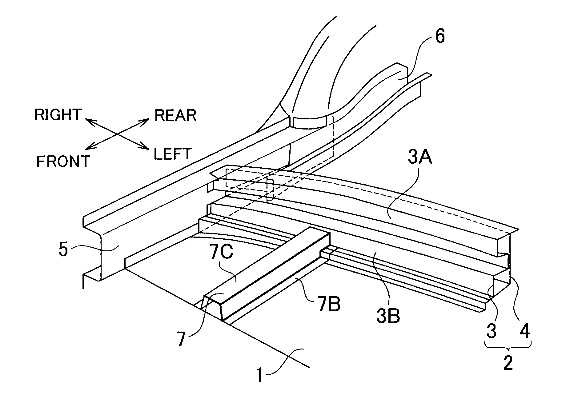
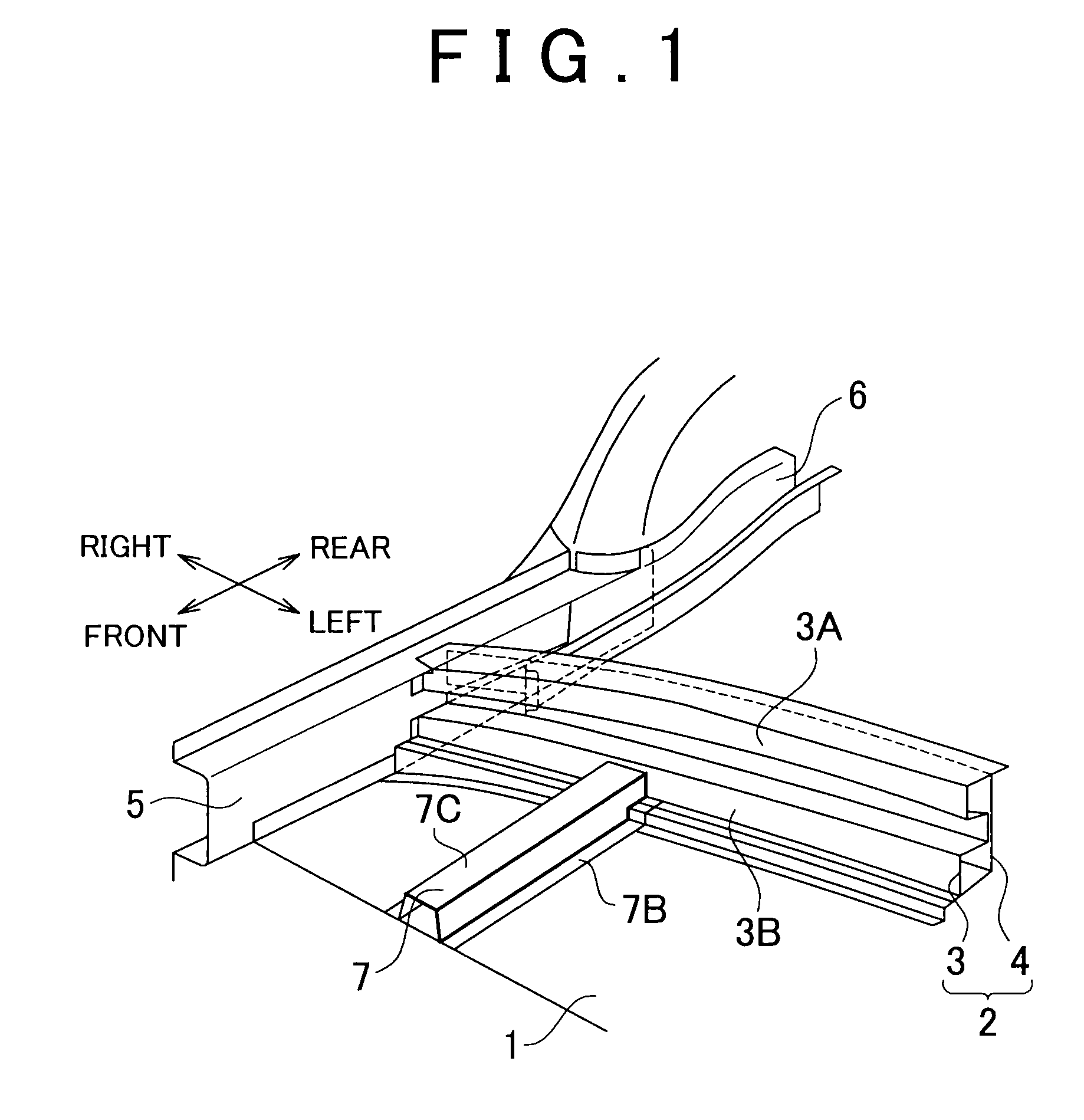
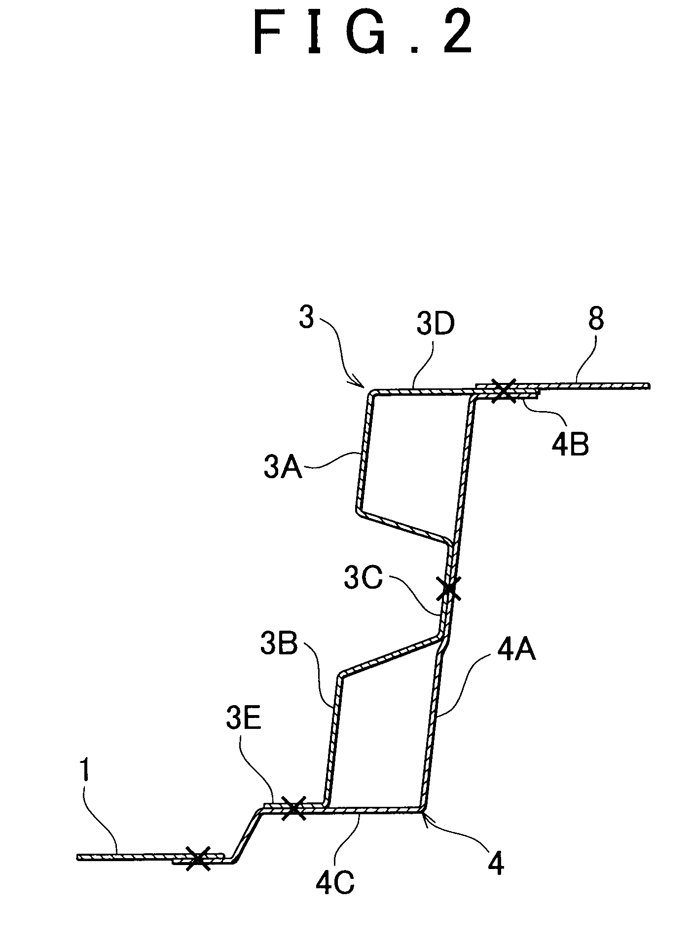
[0025]The vehicle lower body structure according to the invention is, for example, a structure of a lower portion of a vehicle compartment of an automobile. As shown in FIG. 1, at a rear portion of a front floor (floor panel) 1 that forms a lower portion of the vehicle compartment, a center floor cross member 2 is arranged as a cross member that forms a step portion which extends upward from the front floor 1. The center floor cross member 2 is formed of a front cross member 3 that is a first cross member which defines part of the vehicle compartment and which faces the front of a vehicle body, and a rear cross member 4 that is a second cross member which is connected to the rear face of the front cross member 3.
[0026]A right portion and a left portion (left portion is not shown) of the front floor 1 are connected to rocker inner members 5 each of which has a hat-shaped cross section, and rear floor side members 6 are connected to rear portions of the rocker inner members 5. Paired ...
second embodiment
[0044]FIG. 5 is a vertical cross-sectional view showing a cross member of a vehicle lower body structure according to the invention.
[0045]The second embodiment differs from the first embodiment in that a flat front cross member 13 is used instead of the front cross member 3 that has the corrugated cross section, and a rear cross member 14 that has a corrugated cross section is used instead of the flat rear cross member 4.
[0046]The rear cross member 14 is formed in such a manner that projection face portions 14A and 14B that form the corrugations project toward the rear of the vehicle body. The rear cross member 14 forms a plurality of closed section portions in cooperation with the front cross member 13.
[0047]More specifically, a vertical wall portion 13A that forms a flat portion of the front cross member 13 is connected to the front face of a recessed face portion 14C that is formed between an upper projection face portion 14A and a lower projection face portion 14B of the rear cr...
third embodiment
[0051]FIG. 6 is a vertical cross-sectional view showing a cross member of a vehicle lower body structure according to the invention.
[0052]The third embodiment differs from the second embodiment in that a rear cross member 24 is used instead of the rear cross member 14. The front floor 1 in the second embodiment has an extended portion that extends rearward. The rear cross member 24 is formed by bending the extended portion of the front floor 1 in such a manner that the projection face portions 14A and 14B are formed as in the second embodiment. The third embodiment differs from the second embodiment in that the rear cross member 24 is formed integrally with the front floor 1.
[0053]Therefore, instead of the front cross member 13 that is connected at the lower connection portion 13E to the front floor 1, a front cross member 23 is used. A lower portion of the vertical wall portion 13A of the front cross member 23 is connected to a lower portion (portion that is lower than the lower pr...
PUM
 Abstract
Description
Claims
Application Information
 - R&D
- Intellectual Property
- Life Sciences
- Materials
- Tech Scout
- Unparalleled Data Quality
- Higher Quality Content
- 60% Fewer Hallucinations
Browse by: Latest US Patents, China's latest patents, Technical Efficacy Thesaurus, Application Domain, Technology Topic, Popular Technical Reports.
© 2025 PatSnap. All rights reserved.Legal|Privacy policy|Modern Slavery Act Transparency Statement|Sitemap|About US| Contact US: help@patsnap.com


