Idling-stop cancellation control apparatus of vehicle driving system
a technology of cancellation control and vehicle driving system, which is applied in the direction of gearing control, gearing element, belt/chain/gearring, etc., can solve the problems of deteriorating transmission durability, affecting vehicle driveability, and not being able to accurately detect the actual hydraulic pressure of the shift control device by the hydraulic pressure sensor system,
- Summary
- Abstract
- Description
- Claims
- Application Information
AI Technical Summary
Benefits of technology
Problems solved by technology
Method used
Image
Examples
first embodiment
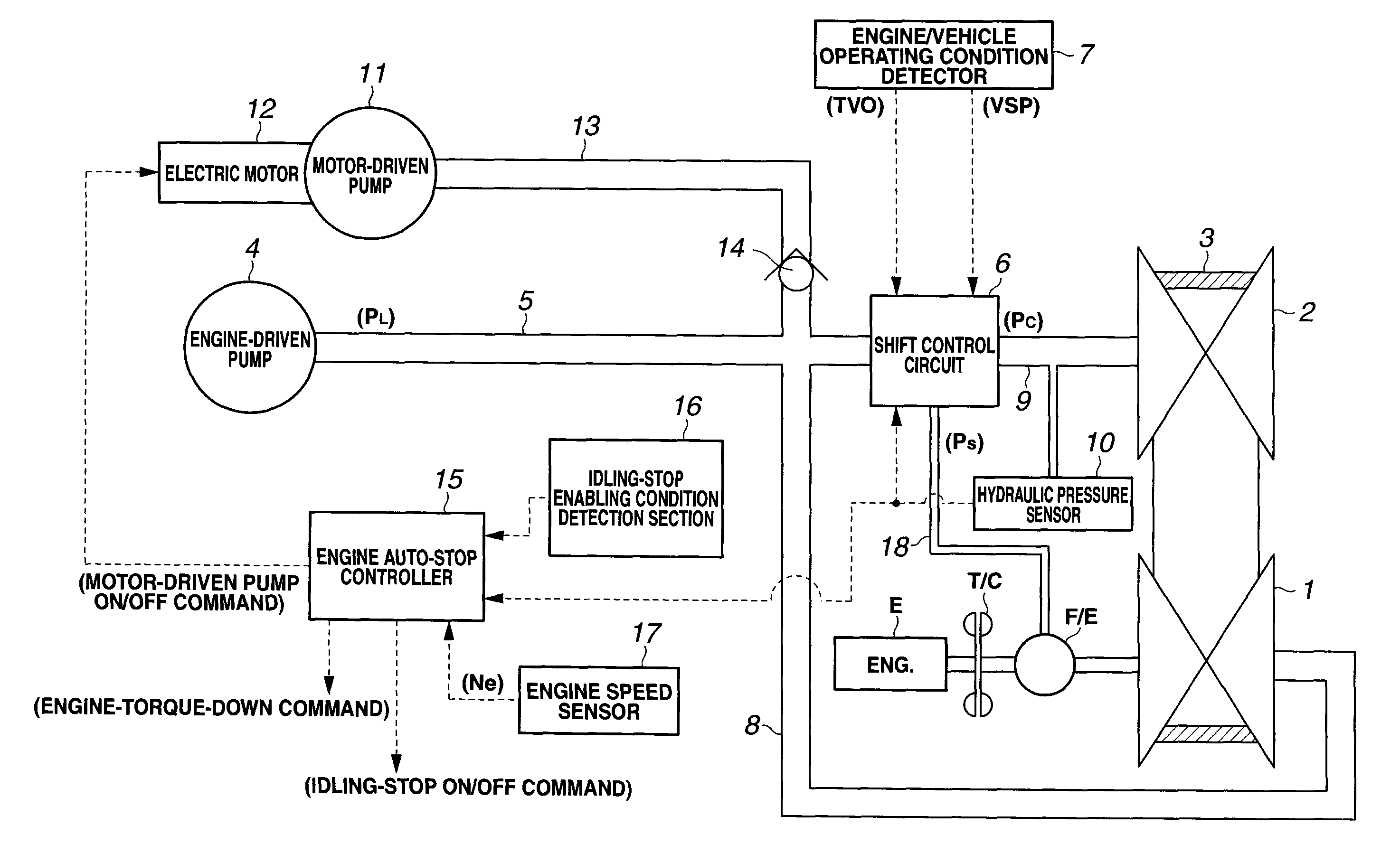
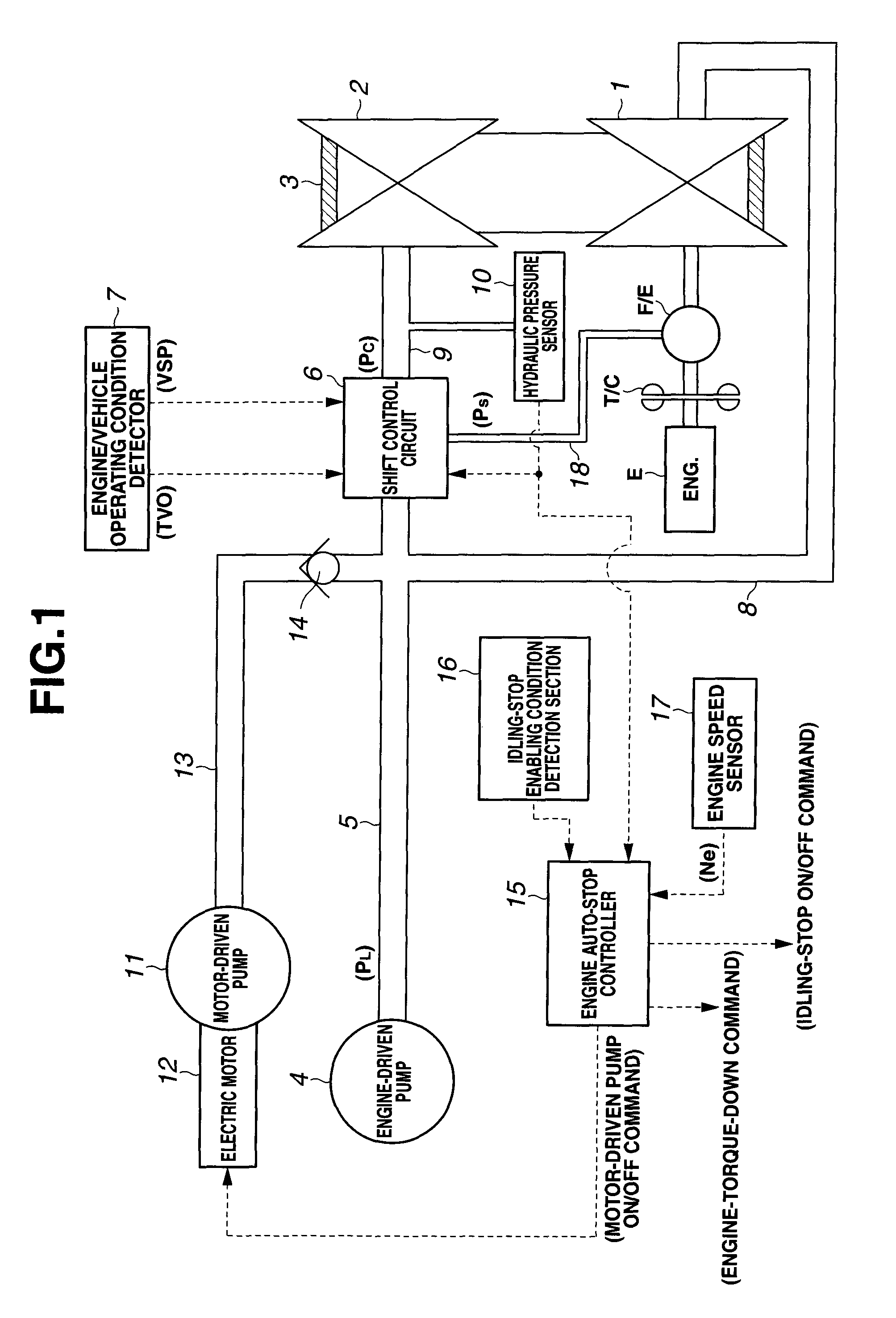
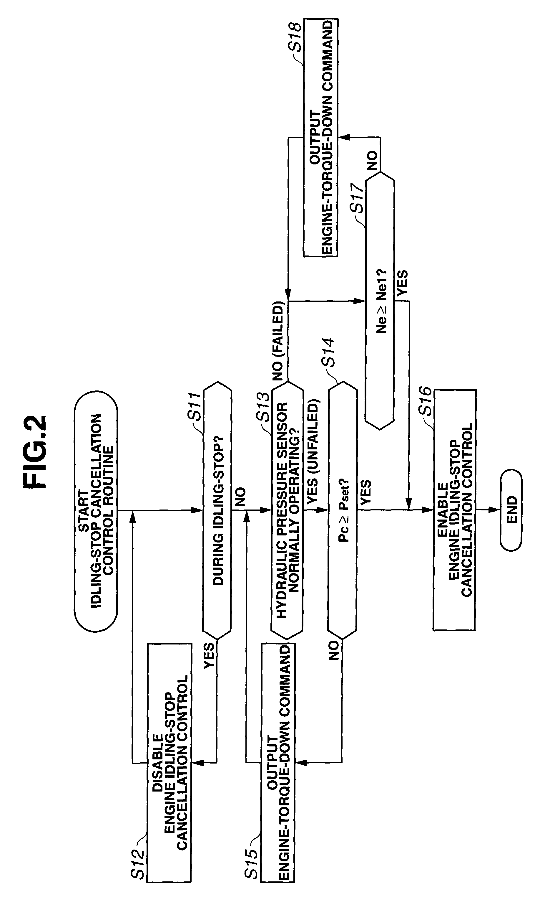
[0067]Referring now to FIG. 2, there is shown the idling-stop cancellation control routine executed within engine auto-stop controller 15 incorporated in the idling-stop cancellation control apparatus of the The routine shown in FIG. 2 is executed as time-triggered interrupt routines to be triggered every predetermined time intervals.
[0068]At step S11, a check is made to determine whether engine E is in its idling-stop state. When the answer to step S1 is in the affirmative (YES), that is, during idling-stop operation of engine E, the routine proceeds from step S11 to step S12. Conversely when the answer to step S11 is in the negative (NO), that is, when engine E is out of the idling-stop state, the routine proceeds from step S11 to step S13.
[0069]At step S12, controller 15 inhibits idling-stop cancellation control by which the vehicle driving system (containing engine E) is put into an engine power output state suited for vehicle-driving operation (simply, a vehicle-driving enabli...
second embodiment
[0099]Referring now to FIG. 4, there is shown the idling-stop cancellation control routine executed within engine auto-stop controller 15 incorporated in the idling-stop cancellation control apparatus of the The routine shown in FIG. 4 is also executed as time-triggered interrupt routines to be triggered every predetermined time intervals. The idling-stop cancellation control routine of FIG. 4 is similar to the control routine of FIG. 2, except that step S17 included in the routine shown in FIG. 2 is replaced with steps S21-S24 included in the routine shown in FIG. 4. Thus, the same step numbers used to designate steps in the routine shown in FIG. 2 will be applied to the corresponding step numbers used in the routine shown in FIG. 4, for the purpose of comparison of the two different interrupt routines. Steps S21-S24 will be hereinafter described in detail with reference to the accompanying drawings, while detailed description of steps S11-S16 and S18 will be omitted because the a...
PUM
 Abstract
Description
Claims
Application Information
 - R&D
- Intellectual Property
- Life Sciences
- Materials
- Tech Scout
- Unparalleled Data Quality
- Higher Quality Content
- 60% Fewer Hallucinations
Browse by: Latest US Patents, China's latest patents, Technical Efficacy Thesaurus, Application Domain, Technology Topic, Popular Technical Reports.
© 2025 PatSnap. All rights reserved.Legal|Privacy policy|Modern Slavery Act Transparency Statement|Sitemap|About US| Contact US: help@patsnap.com


