Contact lens case
a contact lens and case technology, applied in the field of contact lens cases, can solve the problems of bulky design of samples and need more spa
- Summary
- Abstract
- Description
- Claims
- Application Information
AI Technical Summary
Benefits of technology
Problems solved by technology
Method used
Image


Examples
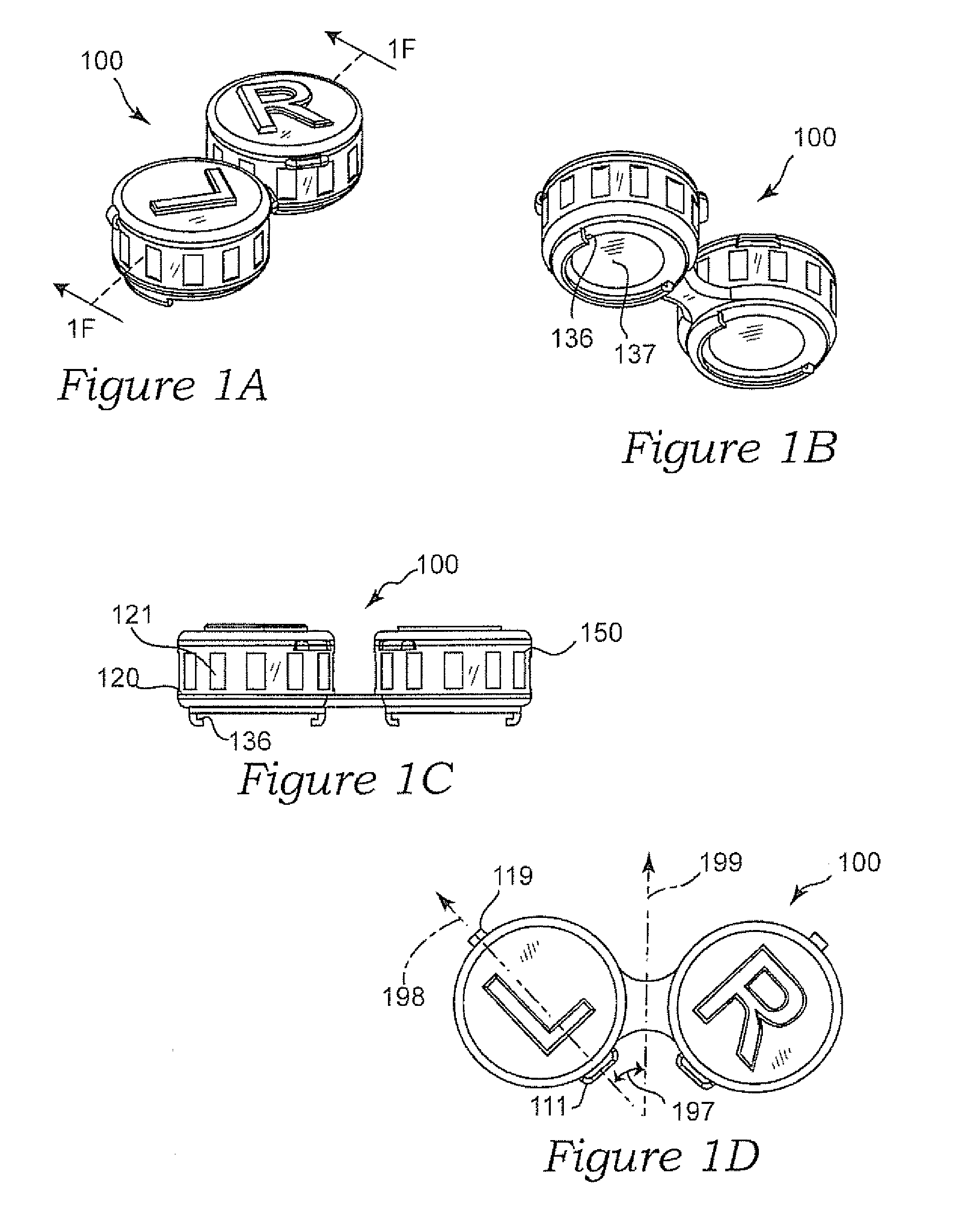
embodiment 100
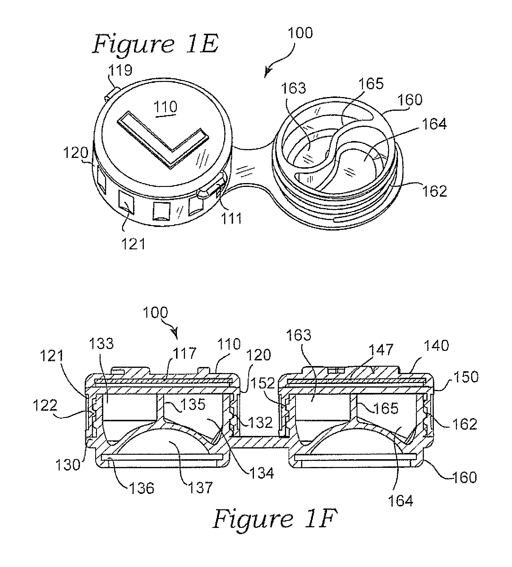
[0037]Referring to FIG. 1E, the second 160 (and first 130) circular base further comprise two reservoirs 163, 164 separated by an S shaped partitioning wall 165. As shown, the two reservoirs 163, 164 together forming a yin yang shape. In this embodiment 100, the first and second base portions 130, 160 would have identically shaped compartments. Additionally as shown, first hinge 119 is comprised of pliable material to connect the first hinged cap 110 to the first threaded cap 120. It is further completed that the entire device 100 can be comprised of biodegradable material.
[0038]Referring to FIG. 2, a sectional view of an additional embodiment of a contact lens case 200 is shown. Herein, the first circular base 230 further comprises two identical bowl shaped reservoirs 233, 234 separated by a partitioning wall 235 configured to store a contact lenses. As expected, second base portion 260 has two identical bowl shaped reservoirs 263, 264 separated by their partitioning wall 265.
embodiment 300
[0039]Referring to FIG. 3, another embodiment 300 is illustrated. Herein, thumb tabs 311, 341 are offset as in FIG. 1D, however pliable hinges 319 and 349 are aligned with what would be the horizontal axis by comparison to FIG. 1D. Also, cap 310 has a reflective surface 317 on an underside thereof.
[0040]Now with reference to FIG. 4A, another embodiment 400 for a contact lens storage case is illustrated. This may be one of two storage units needed as shown by the “R” designation 415, or alternatively, the same design could be made to fit left and right contact lenses. The figure (FIG. 4A) also includes novel thumb latches 411, 421 also having two compartments directly on top of one another in the same footprint. The two compartments initially comprise first and second base portions 420, 430, respectfully.
[0041]Referring, to FIG. 4B the first and second base portions 420, 430 each comprise a bowl-shaped reservoir 423, 433 for storing contact lenses. Cap 410 is provided to secure the u...
PUM
 Abstract
Description
Claims
Application Information
 - R&D
- Intellectual Property
- Life Sciences
- Materials
- Tech Scout
- Unparalleled Data Quality
- Higher Quality Content
- 60% Fewer Hallucinations
Browse by: Latest US Patents, China's latest patents, Technical Efficacy Thesaurus, Application Domain, Technology Topic, Popular Technical Reports.
© 2025 PatSnap. All rights reserved.Legal|Privacy policy|Modern Slavery Act Transparency Statement|Sitemap|About US| Contact US: help@patsnap.com