
Connecting member

a technology of connecting member and connector, which is applied in the direction of electrical apparatus casing/cabinet/drawer, coupling device connection, gaseous cathode, etc., can solve the problem of occupying a large space for the excess portion of the cabl

Inactive Publication Date: 2012-08-21
HONG FU JIN PRECISION IND (SHENZHEN) CO LTD +1
View PDF4 Cites 0 Cited by
  • Summary
  • Abstract
  • Description
  • Claims
  • Application Information

AI Technical Summary

Benefits of technology

The present disclosure relates to a connecting member for electronic components in an electronic device. The connecting member includes a shaft assembly member, an enclosure, a cable, and an elastic member. The shaft assembly member has two shaft members with receiving slots and a positioning block. The cable has two ends, and the elastic member is designed to enclose the shaft assembly member and secure the cable to the shaft assembly member. The elastic member has a first end and a second end, and the second end is designed to engage in the clipping slot of the shaft assembly member. The elastic member can be clipped into the positioning slot of the shaft assembly member, and the top cover of the elastic member can be covered on the elastic member. The technical effect of this invention is to provide a more efficient and organized way to connect electronic components in electronic devices.

Problems solved by technology

The surplus portion of the cable takes up a lot of space in the housing, between these electronic components and can be disorderly placed in the electronic device.

Method used


Image

  • Connecting member
  • Connecting member
  • Connecting member

Examples


Embodiment Construction

[0013]The disclosure is illustrated by way of example and not by way of limitation in the figures of the accompanying drawings in which like references indicate similar elements. It should be noted that references to “an” or “one” embodiment in this disclosure are not necessarily to the same embodiment, and such references mean at least one.

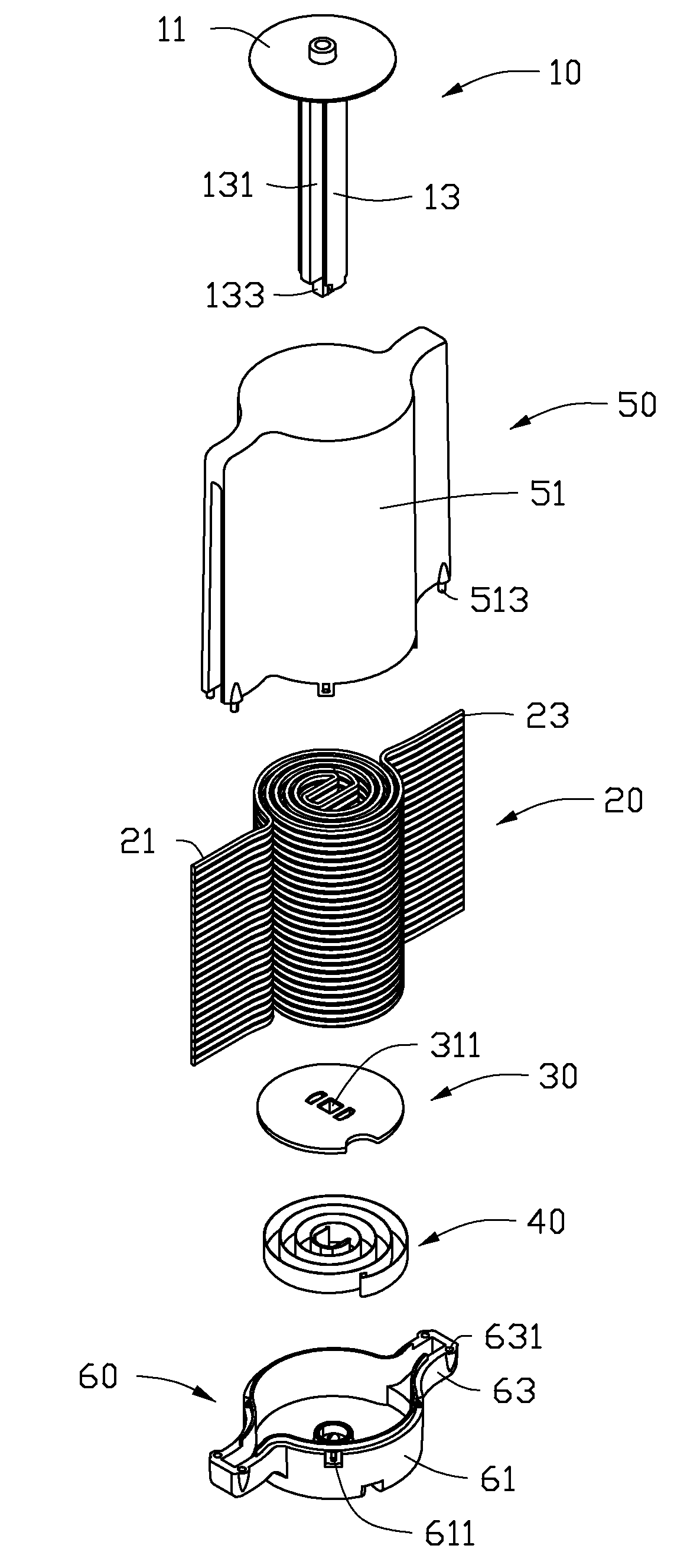
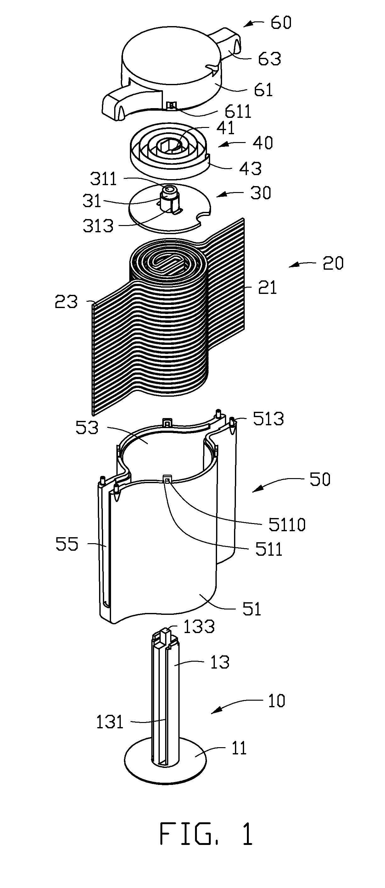
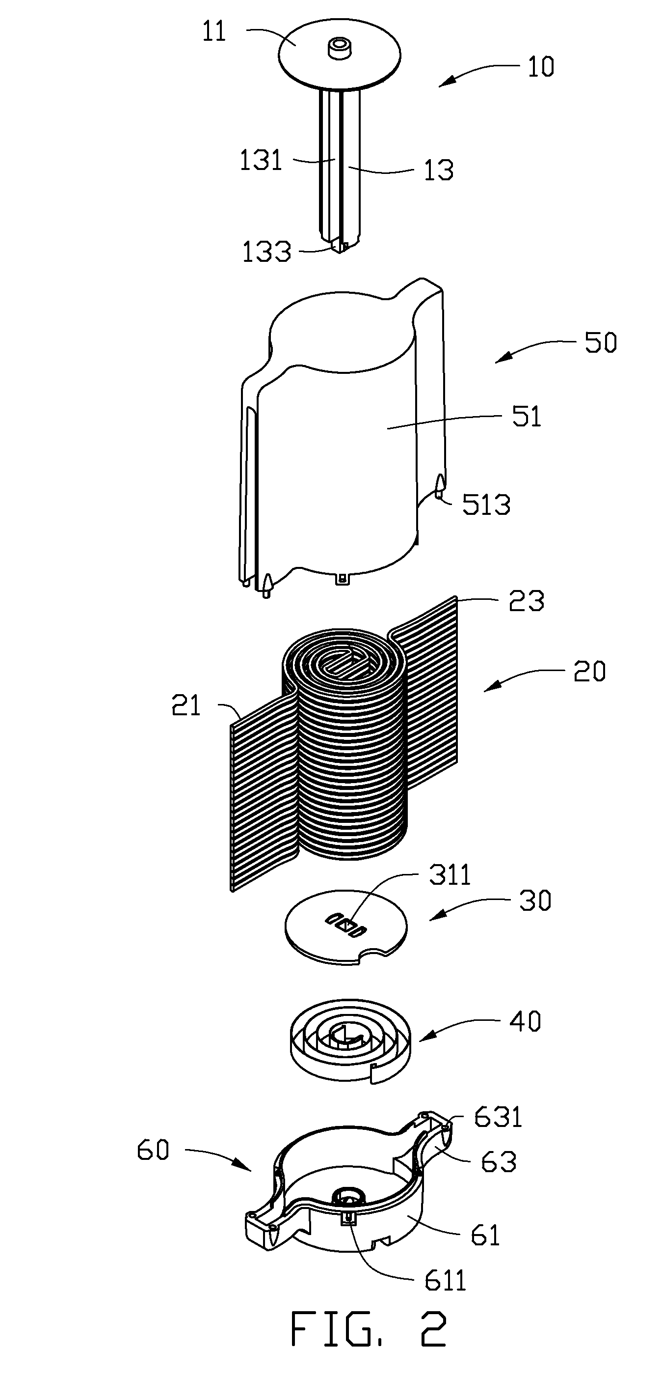
[0014]Referring to FIGS. 1 and 2, a connecting member in accordance with an embodiment includes a shaft assembly member 100 (shown in FIG. 4), an enclosure 200 configured for receiving the shaft assembly member 100 (shown in FIG. 7), a cable 20 and an elastic member 40.

[0015]The shaft assembly member 100 includes a first shaft member 10 and a second shaft member 30 secured to the first shaft member 10. A bottom base 11 and a shaft portion 13 are disposed on the first shaft member 10. In one embodiment, the bottom base 11 is round. Two receiving slots 131 are defined in two opposite sides of the shaft portion 13, and a positioning block 133 is dis...


PUM


Abstract

A connecting member includes a cable, an enclosure, a shaft assembly member and an elastic member. The cable surrounds the shaft assembly member. The shaft assembly member is rotatablely mounted in the enclosure. The elastic member includes a first end and a second end. The first end is secured to the shaft member, and the second end is secured to the enclosure.

Description

BACKGROUND[0001]1. Technical Field[0002]The present disclosure relates to a connecting member for connecting two electronic components of an electronic device.[0003]2. Description of Related Art[0004]Generally, a cable is configured for connecting electronic components, such as a hard disk, a motherboard, or an optical disk drive in order for them to operate. The cable normally has a surplus portion when connected to the electronic components in order to assure the different distances between each component. The surplus portion of the cable takes up a lot of space in the housing, between these electronic components and can be disorderly placed in the electronic device.BRIEF DESCRIPTION OF THE DRAWINGS[0005]Many aspects of the embodiments can be better understood with references to the following drawings. The components in the drawings are not necessarily drawn to scale, the emphasis instead being placed upon clearly illustrating the principles of the embodiments. Moreover, in the dr...

Claims


Application Information

Patent Timeline
Patent Type & Authority Patents(United States)
IPC IPC(8): H01R13/72
CPCB65H75/48H02G11/02B65H2701/34
Inventor LI, ZHAN-YANGYANG, XU
Owner HONG FU JIN PRECISION IND (SHENZHEN) CO LTD
Learn More