Card ejection unit of an improved IC card device

a technology of ic card and ejection unit, which is applied in the direction of coupling device connection, instruments, conveying record carriers, etc., can solve the problems of large space occupied by gears and motors, complicated design of conventional card ejectors, and increased so as to prevent accidental ejection of ic cards, avoid extra resistance from horizontal buckles, and apply efficiently

Active Publication Date: 2012-08-14
T CONN PRECISION CORP
View PDF5 Cites 0 Cited by
  • Summary
  • Abstract
  • Description
  • Claims
  • Application Information

AI Technical Summary

Benefits of technology

[0009]The present invention provides an simple design for IC card device and a card ejector, which is easy to operate and has the advantages of being light, thin, short and small so as to meet the requirement of the market.
[0011]From the above description, the IC card device and the card ejector unit thereof of the present invention is lighter, thinner, shorter and smaller compared to the conventional art, and the motivation method of the card ejector unit thereof includes a rotation bar between the motor and the horizontal buckle. Thus, the direction of the force exerted by the motor is changed after passing by the rotation bar and directly passes the force onto the horizontal buckle so as to avoid the extra resistance from the horizontal buckle. Accordingly, the motor can be more efficiently applied. Besides, the horizontal buckle comprises a side positioned tightly against a side of the horizontal slide track of the base and thereby buckles the vertical elastic element to prevent any accidental ejection of the IC card.

Problems solved by technology

However, such card ejector takes a larger space and usually applied in the larger machines, for example, the ATM.
However, the design of the conventional card ejector is complicated, and the gears and the motor occupy larger space and cannot meet the need of the miniaturized size.
Although the horizontal bar is buckled to the vertical elastic element, but the horizontal bar is an L shape element and is directly connected to the motor, and therefore it is difficult for the motor to push the bar.
Accordingly, the above short comings of the convention card ejectors neither fits the requirement of miniaturization nor a proper design for ejecting the card, and therefore still a lot of improvements are needed.

Method used


Image

  • Card ejection unit of an improved IC card device
  • Card ejection unit of an improved IC card device
  • Card ejection unit of an improved IC card device

Examples


Embodiment Construction

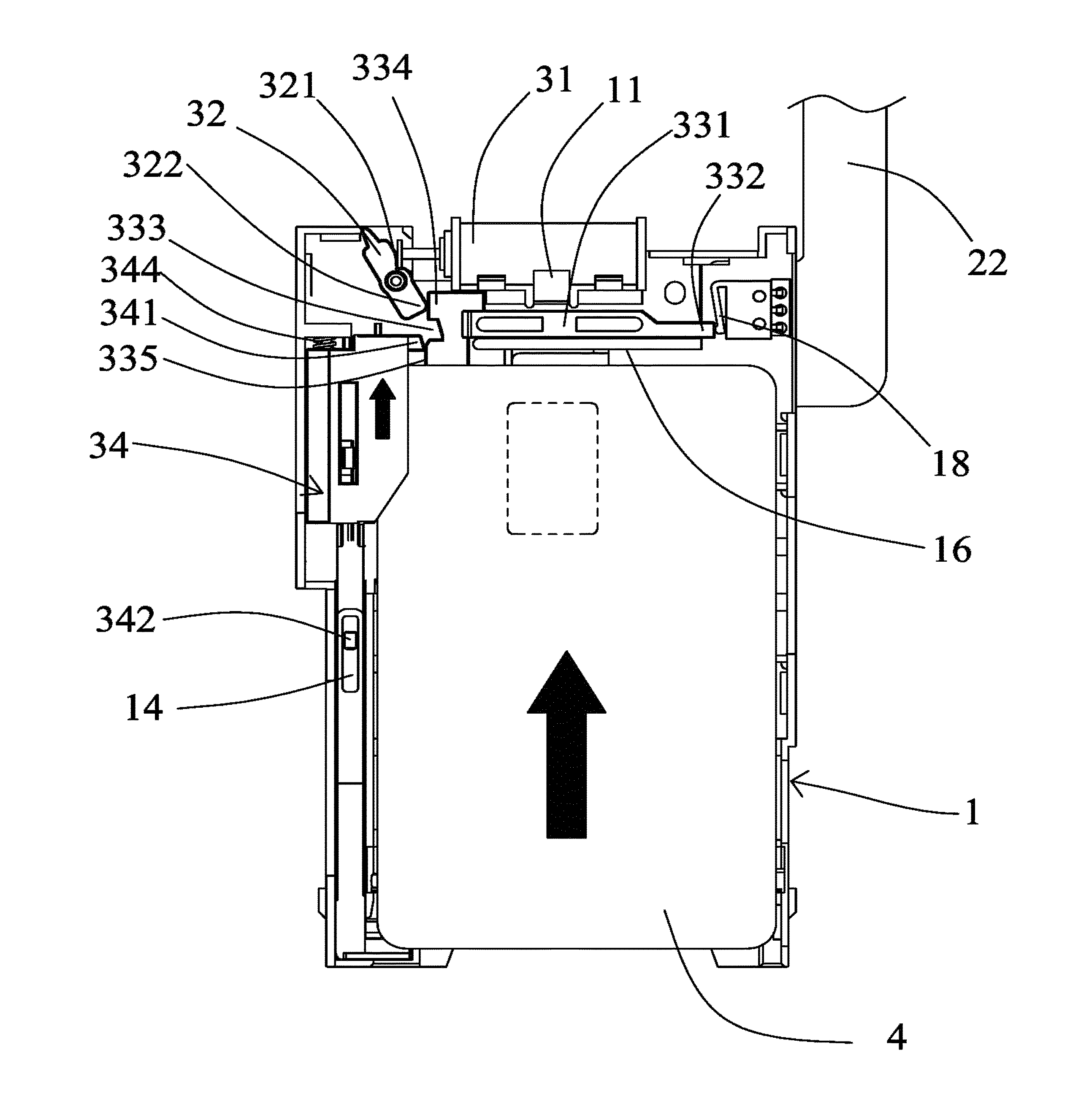
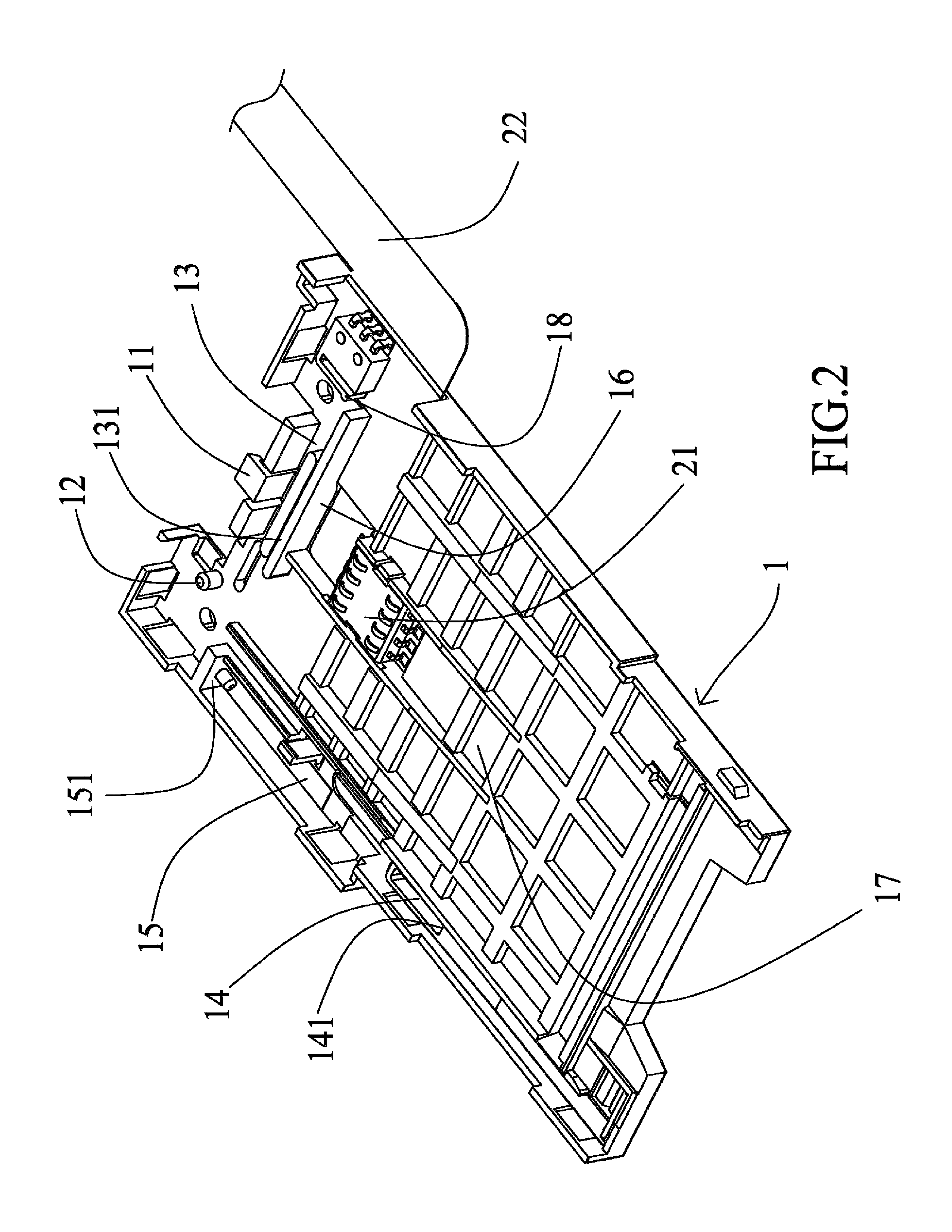
[0023]Referring to FIG. 1, the IC card ejection unit comprises a base 1, a reading unit 2 and a card ejection unit 3. The IC card ejection unit can be applied in a reading device of any IC card or magnetic card. Referring toFIG. 2, the base 1 may be comprised of a plastic or a metallic material. The base 1 comprises a install's member 11 for positioning a motor 31, an axle 12 is positioned adjacent to the install's member 11, and a horizontal slide track 13 is positioned adjacent to the install's member 11. The horizontal slide track 13 comprises a stop 131 at a side thereof. The stop 131 is adopted for providing a support to a slide bar 331 of the horizontal buckle 33. A first spring 18 is positioned adjacent to the horizontal slide track 13. The first spring 18 can be a flat spring, a torsional spring, a compression spring or an expansion spring. The first spring 18 can be positioned on the horizontal buckle 33. The base 1 comprises a vertical slide track 14 positioned on a side. ...


PUM


Abstract

The card ejection unit of an improved IC card device has a base, a reading unit and a card ejection unit. The base has a horizontal slide track, a vertical slide track, a positioning member, an axle and an elastic element. The reading unit has a reading portion, a soft circuit and calculation portion. The card ejection unit has a motor, a rotation bar, a horizontal buckle and a vertical elastic unit. The motor pushes the rotation bar, and when the rotation bar rotates, the push portion of the rotation bar pushes the horizontal buckle to release the vertical elastic element to eject out the IC card.

Description

BACKGROUND OF THE INVENTION[0001]1. Field of the Invention[0002]The present invention relates to an improved IC card device and the card ejection unit thereof; and more particularly to a card ejection unit applied in a data reader.[0003]2. Description of Related Art[0004]The information era has come to lead people living with technology and fashion. Along with the gradually popular related information devices, the electronic card storage device has gradually replaced the conventional identification card and cash, for example, ID card and bills. The identification IC card is being widely used in various public services, for example, the ID card or insurance with IC. People usually use such electronic card storage device for various types of trade related matters in our daily lives, for instance, using credit card for purchasing merchandises, and using ATM card to transfer or withdraw money. Such electronic card storage device has IC or magnetic strip for storing information, and to r...

Claims


Application Information

Patent Timeline
Patent Type & Authority Patents(United States)
IPC IPC(8): G06K5/00
CPCG06K13/08G06K13/0806
Inventor CHEN, SHOU-YIWEI, CHANG
Owner T CONN PRECISION CORP
Why Eureka
Try Eureka