
Bipolar coagulation instrument

a coagulation instrument and bipolar technology, applied in the field of bipolar coagulation instruments, can solve the problems of insufficient suction/flushing capacity of known instruments, difficult installation and high cost, and reduce the free cross-section of hollow shafts that is available for suctioning and/or flushing, etc., to achieve easy and fast suction capacity and facilitate throttle opening handling.

Active Publication Date: 2012-07-31
KARL STORZ GMBH & CO KG
View PDF14 Cites 1 Cited by
  • Summary
  • Abstract
  • Description
  • Claims
  • Application Information

AI Technical Summary

Benefits of technology

The invention is a bipolar coagulation instrument with a unique design. The instrument consists of two electrically conductive tubes that are mounted coaxially on one another and are insulated from each other and the environment. The insulation is achieved by layers of insulating material applied on the inner and outer tubes. The instrument also has a throttle opening that can be opened and closed with one finger for easy handling. The invention allows for a more efficient and compact design of the instrument with a flat and form-locked installation of the insulating layers. The technical effects of the invention include improved suction and flushing capabilities, reduced cabling requirements, and a more compact and easy-to-use design.

Problems solved by technology

The disadvantage with the known bipolar coagulation instruments is that because of the current feeder cable leading to the electrodes positioned on the distal end of the shaft, the free cross-section of the hollow shaft that is available for suctioning and / or flushing is significantly reduced, so that the suction / flushing capacity of the known instruments is insufficient in cases of severe bleeding.
In addition, the known instruments, particularly in the area of the electrodes, have a complex structure, consisting of many individual subcomponents, that makes installation difficult and expensive.

Method used


Image

  • Bipolar coagulation instrument
  • Bipolar coagulation instrument
  • Bipolar coagulation instrument

Examples


Embodiment Construction

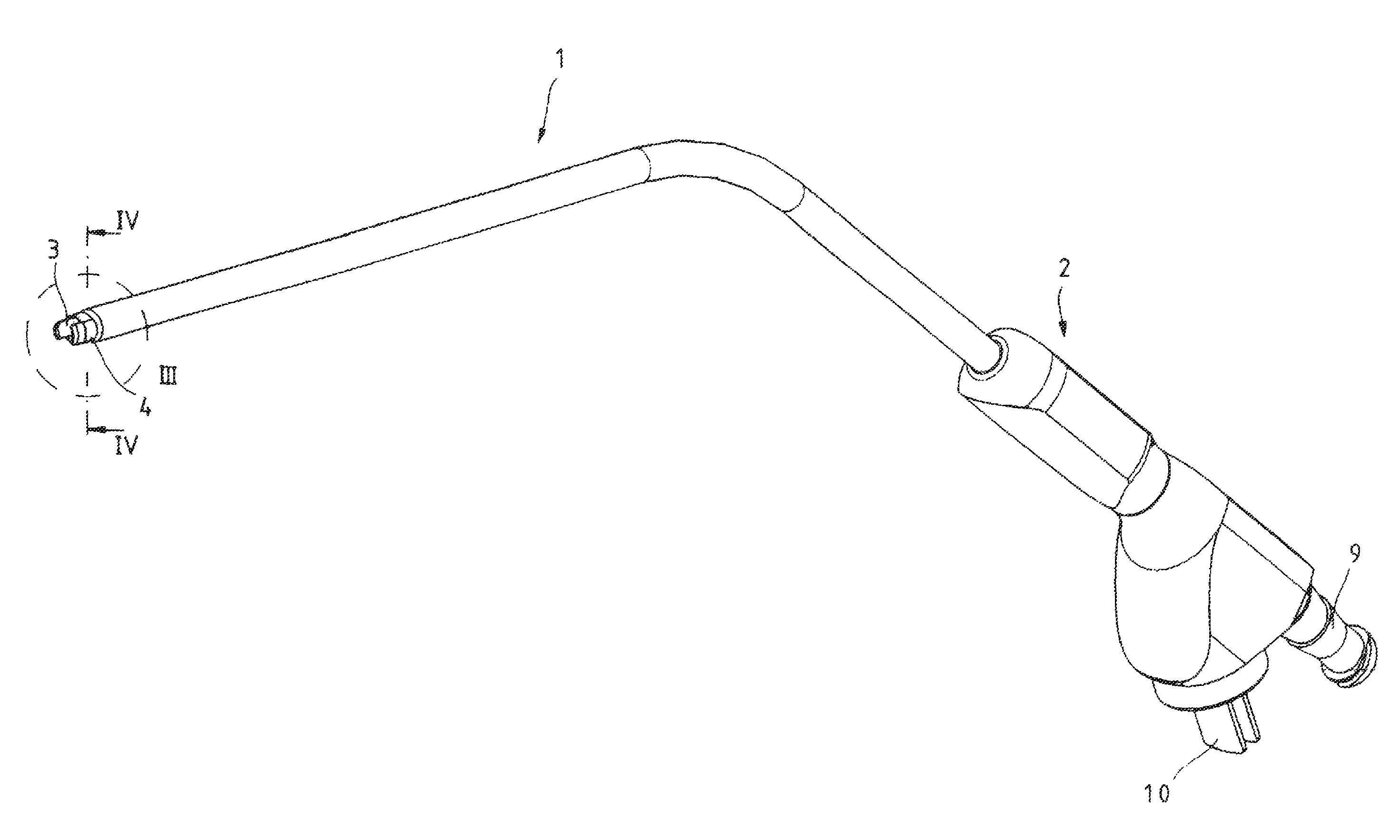
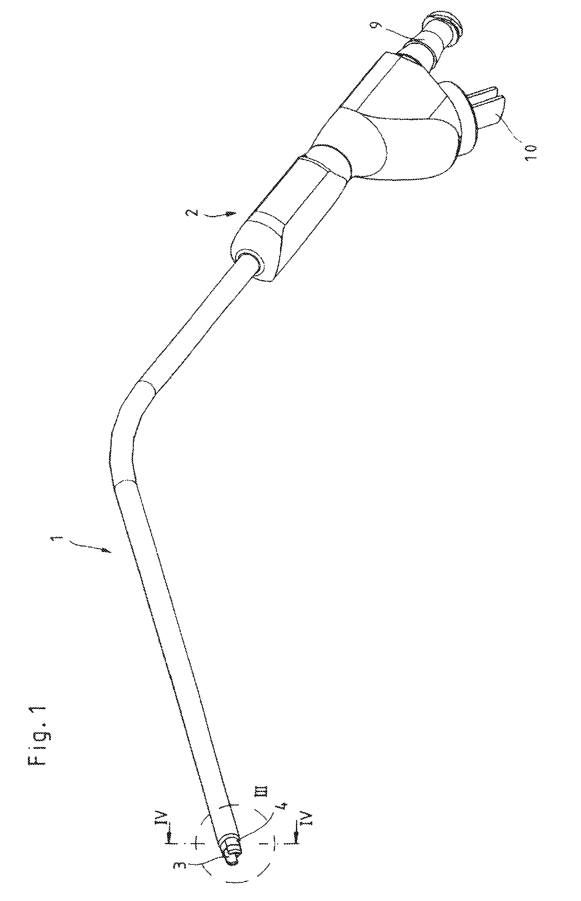
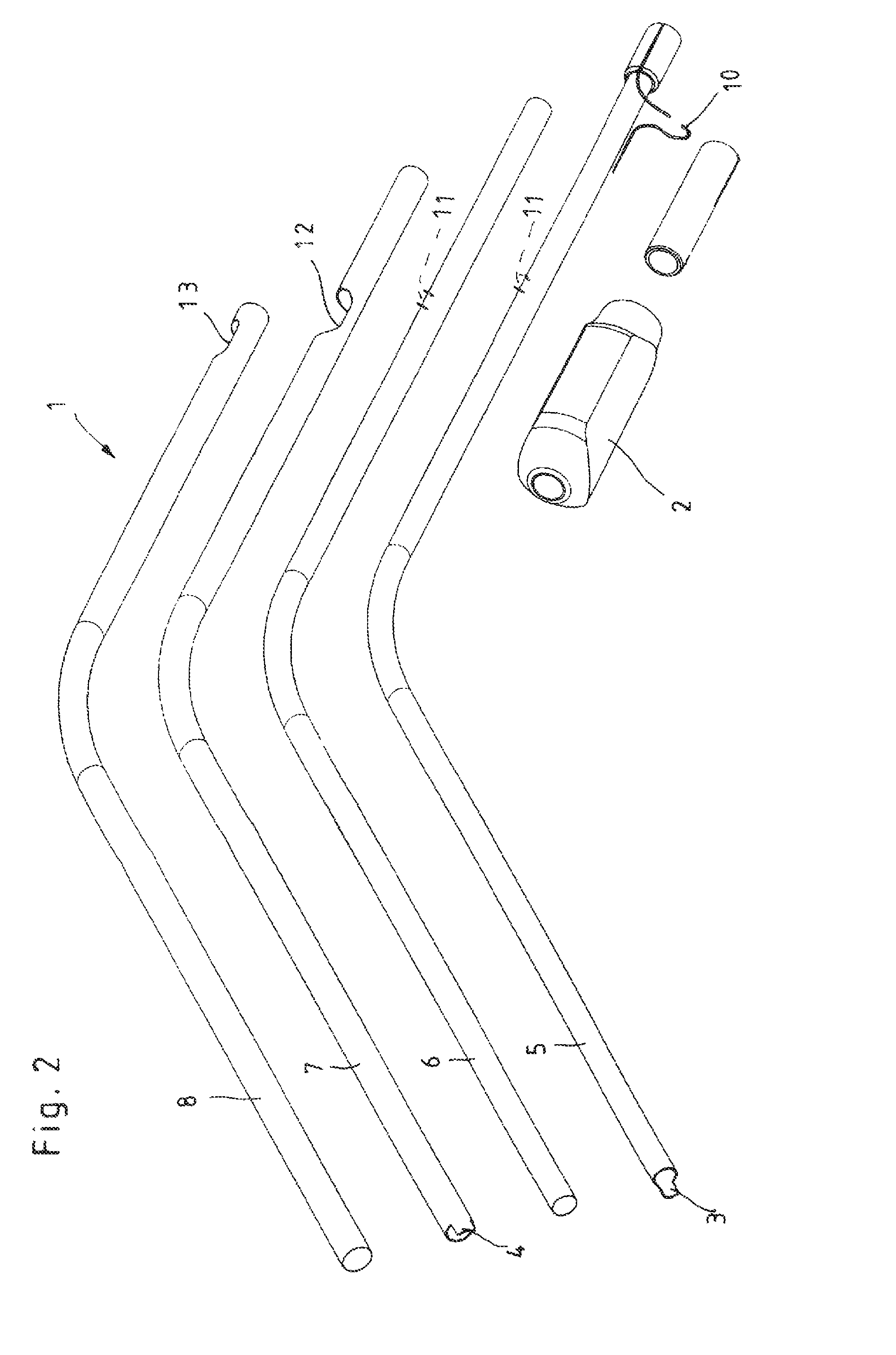
[0025]The medical bipolar coagulation instrument, as shown especially in FIGS. 1 and 2, consists essentially of a hollow shaft 1 configured as a suction / flushing channel, a handle 2 mounted on the proximal end of the shaft 1, and two electrode tips 3 and 4 that extend beyond the hollow shaft 1 on the distal end.

[0026]As can be seen in particular from FIG. 2, the hollow shaft 1 is configured in several layers consisting of an inner tube 5, an electrically insulating layer 6 that coaxially surrounds the inner tube 5, an outer tube 7 that coaxially surrounds the inner tube 5 as well as the insulating layer 6, and an electrically insulating layer 8 that coaxially surrounds the outer tube 7. In the illustrated embodiment the insulating layers 6 and 8, which on the one hand electrically insulate the tubes 5 and 7 with respect to one another and on the other hand electrically insulate the shaft 1 from the outside, are configured as shrink hoses that surround the tubes 5 and 7 in form-locke...


PUM


Abstract

The invention relates to a bipolar coagulation instrument having a hollow shaft configured as a suction and / or flushing tube and having two electrodes that are electrically insulated with respect to one another and extend beyond the distal end of the shaft. To provide a bipolar coagulation instrument that is both of simple structure and ensures an effective suction / flushing capacity, it is proposed with the invention that the hollow shaft should consist of two electrically conductive tubes coaxially mounted on one another that are electrically insulated with respect to one another and from the outside, so that the tubes constitute the electrodes.

Description

CROSS-REFERENCE TO RELATED APPLICATIONS[0001]The present application is a continuation of pending International patent application PCT / EP2009 / 000344 filed on Jan. 21, 2009 which designates the United States and claims priority from German patent application No. 10 2008 006 880.2 filed on Jan. 31, 2008.FIELD OF THE INVENTION[0002]The invention relates to a bipolar coagulation instrument with a hollow shaft configured as a suction and / or flushing tube as well as with two electrodes that are insulated with respect to one another and extend beyond the distal end of the shaft.BACKGROUND OF THE INVENTION[0003]A generic bipolar coagulation instrument is known for instance from DE 44 39 553 C1. These types of bipolar coagulation instruments are used for instance in paranasal surgery in addition to coagulation treatment to close vessels by means of electrodes charged with current. The combination of a bipolar coagulation instrument and a suction and / or flushing instrument is advantageous bec...

Claims


Application Information

Patent Timeline
Patent Type & Authority Patents(United States)
IPC IPC(8): A61B18/14
CPCA61B18/1482A61B2218/007A61M1/0047A61M1/0058A61M1/7411A61M1/77
Inventor BACHER, UWEHERMLE, RAINER
Owner KARL STORZ GMBH & CO KG
Learn More