
Magnetic stirring system in a pVT cell including driving solenoids and a monitoring solenoid

a technology of magnetic stirring system and monitoring solenoids, which is applied in the direction of mixing, instruments, transportation and packaging, etc., can solve the problems of not being able to see the stirrer, the stirrer may not rotate at the desired frequency, and the fluid cannot be seen, so as to reduce the stray magnetic field

Inactive Publication Date: 2012-07-24
SINVENT AS
View PDF9 Cites 6 Cited by
  • Summary
  • Abstract
  • Description
  • Claims
  • Application Information

AI Technical Summary

Benefits of technology

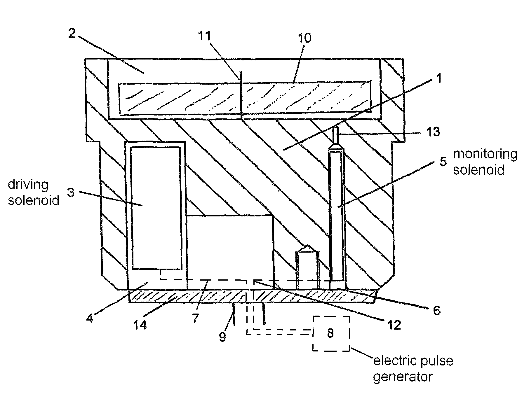
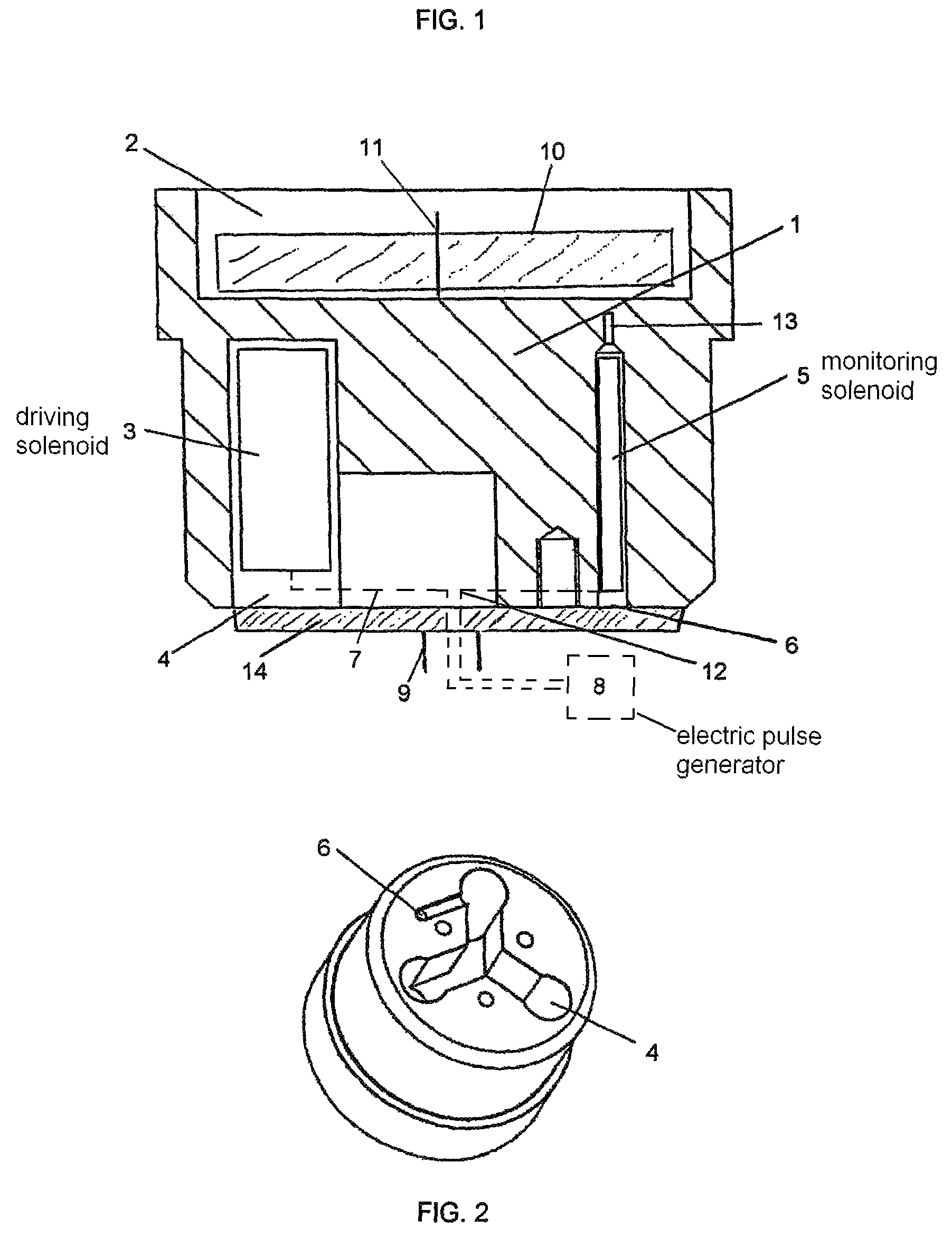
[0021]The pVT cell may preferably be configured such that all solenoids are removably arranged in wells in a piston rear side opposite to said fluid side. The pVT cell may preferably be configured such that at least one of said monitoring solenoid and said driving solenoids is fitted with axially extended core toward said impeller recess, said extended core fitting in a well extension that permits a short minimum distance between said extended core and an impeller permanent magnet, thereby reducing stray magnetic fields. The pVT cell may preferably be configured such that said monitoring solenoid is connected by wiring to an external pulse indicator. The pVT cell may preferably be configured such that said driving solenoids are connected by wiring to an external pulse generator. The pVT cell may preferably be configured such that said impeller recess covers a substantial part of the fluid side area of the piston. The pVT cell may preferably be configured such that said impeller recess is cylindrical in shape with said shaft being arranged concentrically therein. The pVT cell may preferably further comprise a hollow rod fixed to a piston cover fastened to a piston rear side opposite said fluid side, said rod extending out of said cell, to provide a passage for wiring to and from said piston.

Problems solved by technology

Some petroleum fluids are very viscous, and the stirrer may therefore not rotate at the desired frequency.
Some cells are not provided with a window, and it is therefore not possible to see the fluid (blind cells).
In many cases it would not be possible to see the stirrer even if the cell has a window, because the fluids are so dark.
The shaft driven stirrers are not magnetically coupled, but directly driven, with related sealing problems.

Method used


Image

  • Magnetic stirring system in a pVT cell including driving solenoids and a monitoring solenoid
  • Magnetic stirring system in a pVT cell including driving solenoids and a monitoring solenoid

Examples


Embodiment Construction

[0025]One solution of assuring good stirring is to place a magnetic driven stirring impeller on top of the piston. An impeller 10 with inserted permanent magnets is placed on a shaft 11 in a cavity 2 on the test fluid side of the piston body 1.

[0026]The stirrer is energized by an assembly of solenoids 3 placed inside the piston 1 in separate wells 4 in the piston body, but separated from the fluids. One of these wells 4 is indicated in FIG. 1, while three such wells appear in FIG. 2.

[0027]The solenoids are placed parallel to the piston cylinder axis and with one end of the core pointing to the magnets in the impeller 10, while the opposite sides are magnetically connected to increase field strength and reduce stray fields.

[0028]The piston 1 must be made of a non-magnetic material, preferably an alloy (e.g. Hastelloy C, Inconel, 316 stainless steel etc.). Phased power pulses to the solenoids 3 are supplied by thin Teflon insulated electric wires 7 which are drawn through a hollow rod...


PUM


Abstract

A pVT cell for testing of fluids at high pressure includes a piston (1) and a stirring system for rapidly providing equilibrium prior to test measurement. The stirring system includes: an impeller (10) mounted for rotation on a shaft (11) in an impeller recess (2) on a fluid side of said piston (1), said impeller (10) including at least one permanent magnet; at least two driving solenoids (3) inside said piston (1) for influencing said at least one permanent magnet and thereby providing impeller (10) movement; and a monitoring solenoid (5) arranged inside said piston (1) close to but isolated from the impeller recess (2) in order to monitor the rotation of the impeller (10).

Description

[0001]The present application hereby claims priority to U.S. Provisional Application No. 60 / 712,423, filed Aug. 31, 2005.BACKGROUND OF THE INVENTION[0002]1. Technical Field[0003]The present invention relates to a system for stirring by a magnetic coupled impeller, for use in pressure, volume and temperature (pVT) studies, of reservoir fluids and their properties in the laboratory and in the field.[0004]In pVT cells and condensate cells, petroleum fluids can be studied at varying pressure and temperature simulating the conditions in oil reservoirs before and during production. Typically these fluids contain gas. The change in fluid density (compressibility) and the tendency for the gas to come out of the solution at decreasing pressure are of particular interest.[0005]pVT cells are optimized to study oils with dissolved gas, while condensate cells are optimized to study light oils with high gas to oil ratio. In the following description they are both referred to as pVT cells.[0006]Un...

Claims


Application Information

Patent Timeline
Patent Type & Authority Patents(United States)
IPC IPC(8): B01F13/08
CPCB01F13/0059B01F13/0827B01F13/0863B01F15/00201G01N7/00G01N2011/147B01F33/30B01F33/453B01F33/4534B01F35/212
Inventor LINDEBERG, ERIK GOSTA BRUNO
Owner SINVENT AS
Learn More