
Light-beam shaper

a technology of light beams and shapers, applied in the field of optical devices, can solve the problems of not being able to install street luminaries, affecting the appearance of street luminaries, and being quite bulky in sources

Active Publication Date: 2012-07-17
SIGNIFY HLDG BV
View PDF113 Cites 26 Cited by
  • Summary
  • Abstract
  • Description
  • Claims
  • Application Information

AI Technical Summary

Benefits of technology

The invention provides a street luminary that can light up a street zone evenly without causing glare to users. It also satisfies regulations regarding lighting uniformity, intensity, glare, and sky pollution. The luminary is less sensitive to wind and requires less maintenance. It has a low operating cost. The invention proposes an optical device called a light-beam shaper that can shape the light beam emitted by a light source. A luminary head comprising a plurality of LEDs and a light-beam shaper is also provided. The LEDs and the light-beam shaper are arranged in a way that the light beams are directed towards the same direction, simplifying the manufacture of the luminary heads.

Problems solved by technology

Indeed, due to the traffic, it is not possible to install the street luminaries right over the zones that need to be enlightened, as this would be too dangerous.
Such reflector systems are quite bulky.
However, these kinds of sources are quite bulky and they require a frequent and time-consuming maintenance.
A consequence of bulkiness is that the luminary heads also are bulky, which may be a drawback under windy conditions.

Method used


Image

  • Light-beam shaper
  • Light-beam shaper
  • Light-beam shaper

Examples


Embodiment Construction

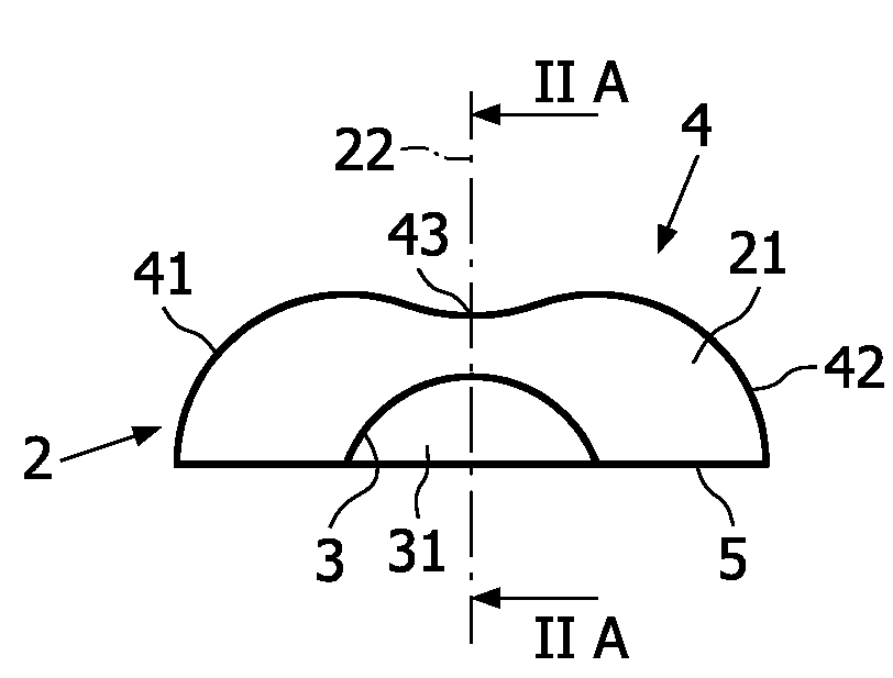
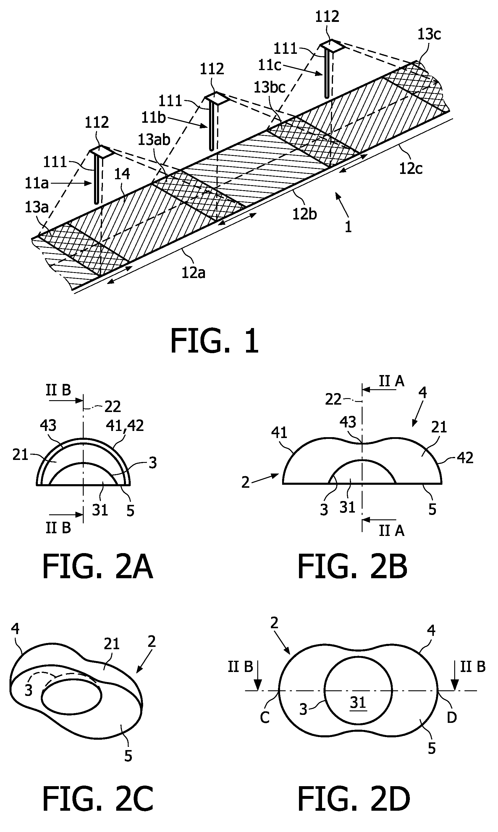
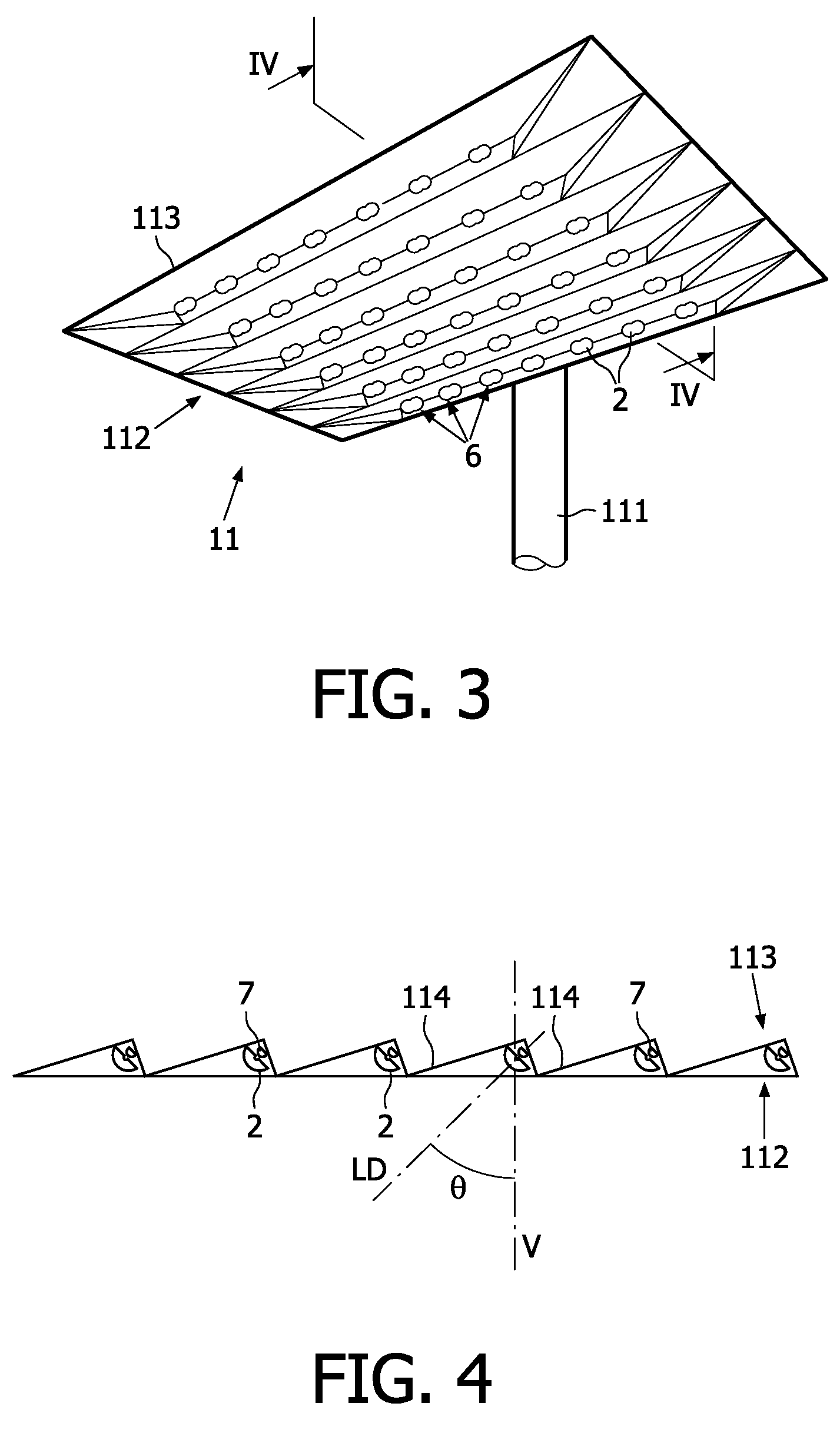
[0022]The following definitions are adopted in this specification. The words “street”, “road”, “motorway” and the like shall be construed as having a similar meaning.

[0023]A diopter is an optical surface which separates two light propagation media having different refractive indices. Examples of light propagation media are, for instance, air, glass, polymethacrylate or other plastics.

[0024]A lens is a device that causes light to either converge or diverge. It is made from a piece of shaped material, such as glass, polymethacrylate or other plastics. Usually, a lens has two faces or diopters. A face, or a part thereof, may be planar (it is not curved), convex (bulging outwards from the lens) or concave (depressed into the lens).

[0025]A quadric is second-order surface. For instance, a sphere has a quadric surface.

[0026]A metasurface is the surface of a metaball.

[0027]A metaball is defined as follows. Each component Ci of a metaball may be defined by a three-dimensional mathematical fu...


PUM


Abstract

The invention relates to an optical device for imparting an elongate shape to a light beam emitted by a LED, and to street luminaries which comprise such optical devices. The optical device comprises a lens (2) having an entry diopter (3) and an exit diopter (4) which comprises a first convergent section, a second convergent section and a divergent section bridging said first and second convergent sections.

Description

FIELD OF THE INVENTION[0001]The invention relates to an optical device for imparting a desired shape to a light beam, this device being also designated as a “light-beam shaper”. This optical device is particularly relevant for lighting surfaces which have a great length with respect to their width, such as a road, a street or a motorway.BACKGROUND OF THE INVENTION[0002]FIG. 1 depicts a schematic perspective view of a road section 1 equipped with three street luminaries 11a, 11b, 11c. The street luminaries, or candelabra, comprise a luminary post 111 and luminary head 112. Each street luminary enlightens a respective street zone 12a, 12b, 12c of the road section 1, each street zone having a length L. These enlightened street zones may be slightly overlapping in overlapping zones 13a, 13ab, 13bc, 13c. Usually as illustrated on FIG. 1, street luminaries are set back from the border 14 of the road section 1. For instance, they are erected on a pavement, on the border 14 of the road sect...

Claims


Application Information

Patent Timeline
Patent Type & Authority Patents(United States)
IPC IPC(8): F21V1/00
CPCG02B27/0955G02B19/0061F21V5/04G02B19/0014F21W2131/103F21Y2101/02F21S8/08F21S2/00F21Y2115/10
Inventor MONTAGNE, LOUIS
Owner SIGNIFY HLDG BV
Learn More