
Electric load damper for damping torsional oscillation

a technology of torsional oscillation and load damping, which is applied in the direction of electric motor propulsion transmission, electric generator control, dynamo-electric converter control, etc., can solve the problems of undesirable torsional oscillation and mechanical failure in the system, over-all negative damping, and mechanical damping that requires additional hardware and mechanical components, so as to selectively reduce the torsional oscillation of the shaft

Active Publication Date: 2012-07-10
HAMILTON SUNDSTRAND CORP
View PDF34 Cites 14 Cited by
  • Summary
  • Abstract
  • Description
  • Claims
  • Application Information

AI Technical Summary

Problems solved by technology

Engine gearboxes may exhibit lightly damped characteristics, resulting in overall negative damping when coupled to a high power generator or generators due to their electromechanical torque characteristics for disturbance frequencies that are within the generator's voltage regulation bandwidth.
In certain situations, depending on factors such as generator speed, generator electrical load, and net effective damping in the overall mechanical drive train, the torsional resonance of the spring-mass system involving the generator or generators can lead to large, undesirable torsional oscillations and mechanical failures in the system.
Although mechanical damping may be used to offset the negative damping characteristic of the synchronous generator or generators and thus dampen the torsional oscillations in the spring-mass system, mechanical damping requires additional hardware and mechanical components that can increase the weight and cost of a system.

Method used


Image

  • Electric load damper for damping torsional oscillation
  • Electric load damper for damping torsional oscillation
  • Electric load damper for damping torsional oscillation

Examples


Embodiment Construction

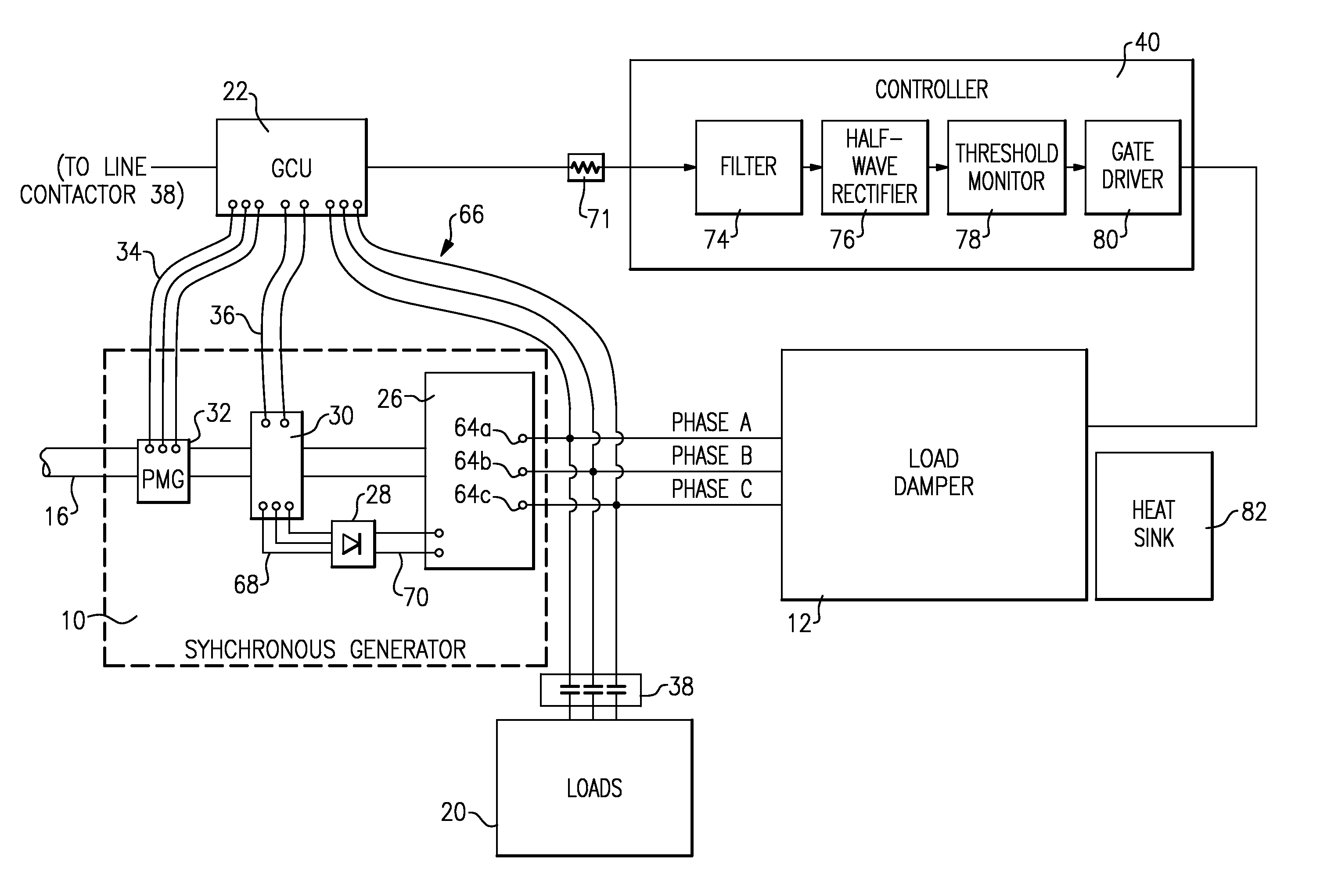
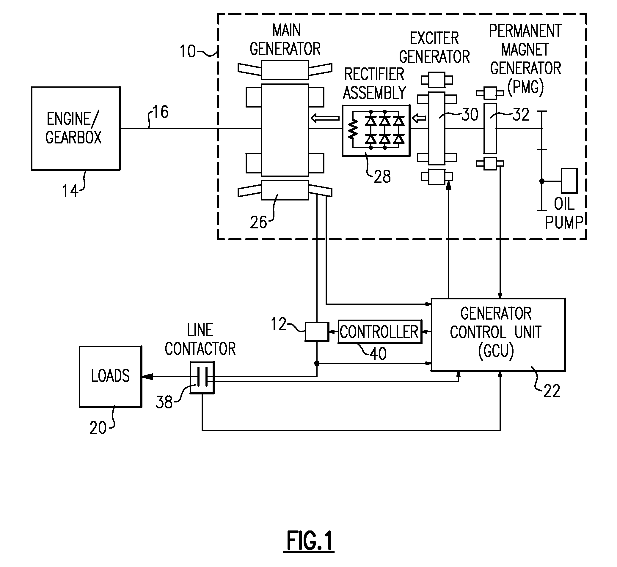
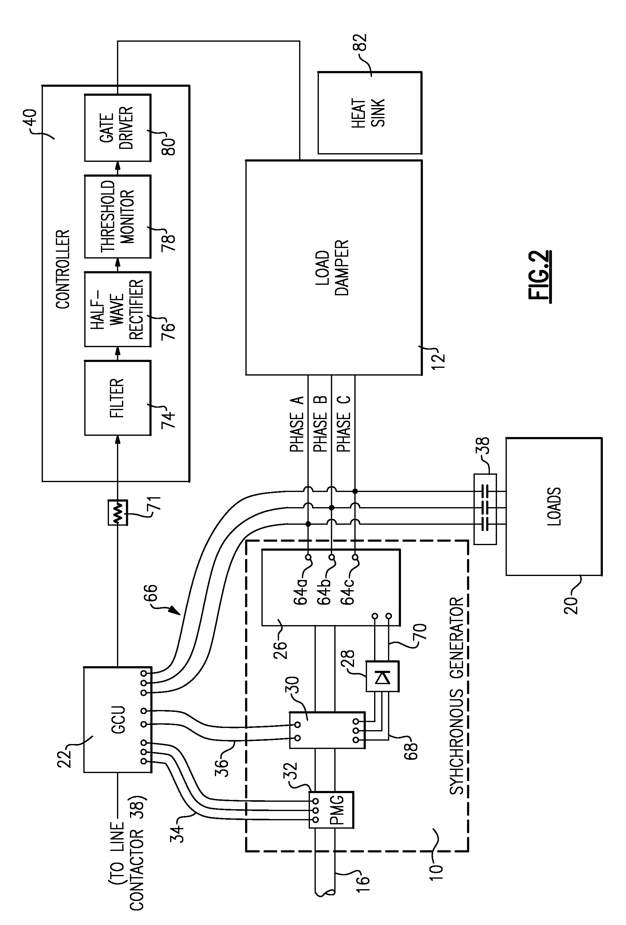
[0017]FIG. 1 schematically illustrates a drive schematic for a synchronous generator 10 that utilizes a load damper 12. An engine / gear box 14 transmits rotating mechanical power along a shaft 16 to the synchronous generator 10. The generator 10 uses the mechanical power to generate an electrical output to one or more aircraft loads 20. A generator control unit (“GCU”) 22 monitors the output voltage of the generator 10 and adjusts the voltage to an exciter generator 30 to maintain a desired output voltage.

[0018]The synchronous generator 10 includes a main generator 26, a rotating rectifier assembly 28, the exciter generator 30, and a permanent magnet generator (“PMG”) 32. The main generator 26, exciter 30, and PMG 32 are electrical machines that are either on the shaft 16 or are connected through a gear ratio to the shaft 16. In response to the mechanical power provided by the shaft 16, PMG 32 generates a 3-phase alternating current (“AC”) output voltage that the PMG 32 provides to t...


PUM


Abstract

An electric load damper assembly includes a synchronous generator operable to provide a plurality of phases of electrical output in response to a mechanical input from a rotating shaft. An electric load damper includes a phase leg for each of the plurality of phases. Each phase leg includes a resistive load, a snubber and at least one solid state switch. The at least one solid state switch is in parallel with the snubber, and the at least one solid state switch and snubber are collectively in series with the resistive load. A controller is operable to receive a signal indicative of a rotational speed oscillation of the synchronous generator, and is operable to selectively reduce a torsional oscillation of the shaft by diverting electrical current from the synchronous generator through the resistive load of each of the plurality of phases in response to the signal exceeding a predefined threshold.

Description

BACKGROUND OF THE INVENTION[0001]This application relates to damping torsional oscillation, and more specifically to an electric load damper for damping torsional oscillation.[0002]Synchronous generators are used in a variety of applications to convert mechanical energy provided by an engine to alternating current (“AC”) electrical energy. One example application for a synchronous generator is a gas turbine engine for an aircraft, in which the generator generates AC electrical energy to operate on-board electrical systems.[0003]A gas turbine engine may be used to generate mechanical energy that is provided through a gearbox along a shaft to one or more synchronous generators. Due to a multitude of competing mechanical design considerations, the shaft may be relatively long and mechanically compliant. The inertias associated with the engine, the gearbox, the one or more synchronous generators, and other gearbox driven accessories in combination with the mechanical compliance or sprin...

Claims


Application Information

Patent Timeline
Patent Type & Authority Patents(United States)
IPC IPC(8): H02P11/00H02P9/00H02H7/06B61C9/38B60L11/02B60L50/10
CPCH02P9/102H02P9/302H02P9/16H02P2101/30
Inventor MARKUNAS, ALBERT L.MADALLI, VIJAY K.BAKER, DONAL E.SAGONA, JOHN
Owner HAMILTON SUNDSTRAND CORP
Learn More