
Rheological measurement of filtercake

a filtercake and rheological measurement technology, applied in the direction of instruments, separation processes, wellbore/well accessories, etc., can solve the problems of cake under pressure not being able to simulate typical wellbore drilling conditions, problems such as problems, and cake under pressure remaining intractabl

Inactive Publication Date: 2012-07-10
MI
View PDF4 Cites 3 Cited by
  • Summary
  • Abstract
  • Description
  • Claims
  • Application Information

AI Technical Summary

Benefits of technology

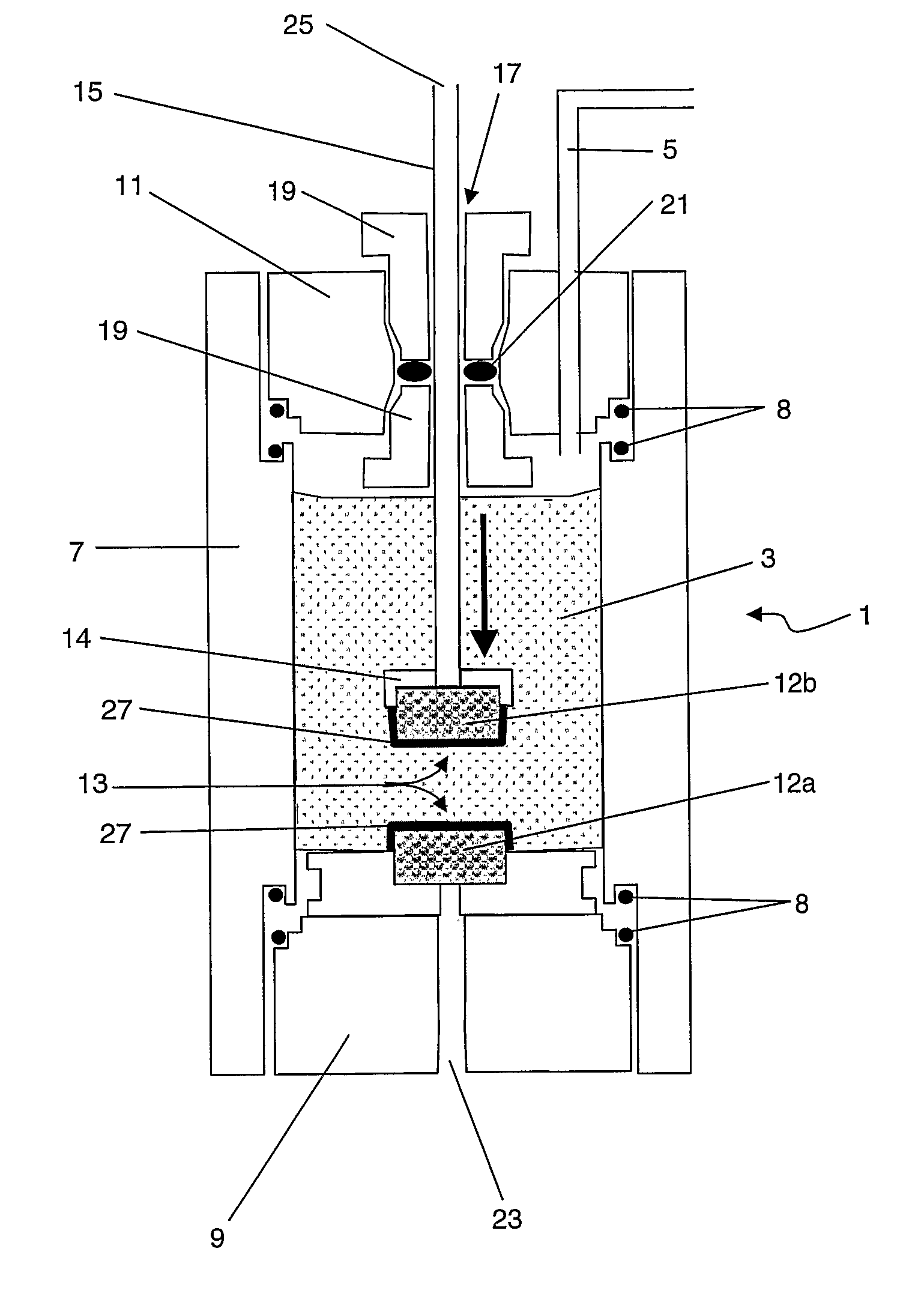
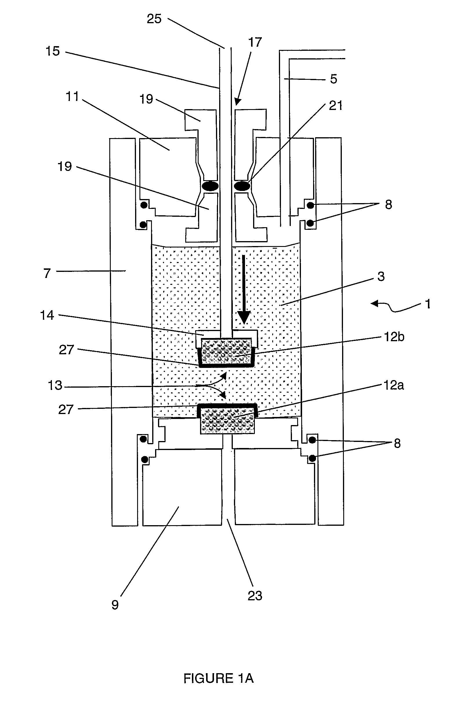
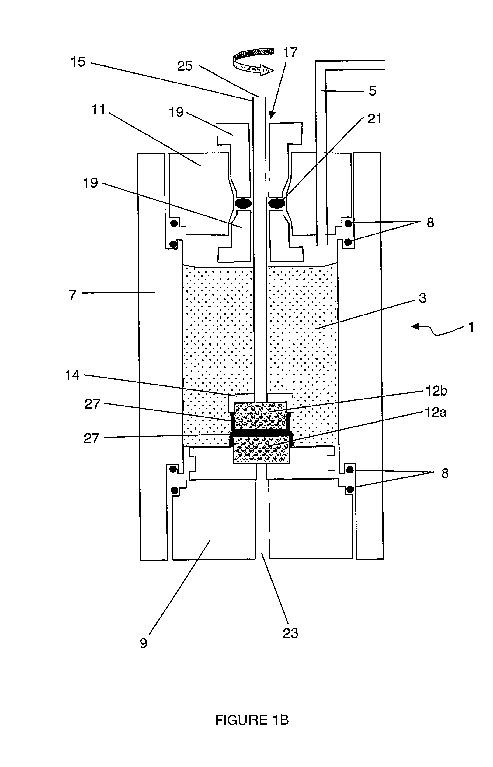
The present invention provides a rheometer and method for measuring the rheological properties of filtercakes formed by drilling mud. The rheometer has two foraminous bodies with adjustable separation between them, allowing for the measurement of filtercakes of different thicknesses. The foraminous bodies are designed to provide a high friction contact with the filtercake, reducing errors in the measurement. The method involves filtering the fluid under pressure through the foraminous bodies to form filtercakes on their surfaces, and then translating or rotating the foraminous bodies to bring the filtercakes together and form a unified filtercake. The unified filtercake can be measured using the rheometer to provide valuable information on the properties of the filtercake during wellbore drilling.

Problems solved by technology

However if the filtercake becomes too thick, problems can occur.
However, the behaviour of the cake under pressure has remained intractable.
However, the measurement is performed on depressurised filtercakes and therefore does not simulate typical wellbore drilling conditions.
A differential pressure is generated across the filter by a vacuum pump, but this method cannot achieve the high pressures typical of well-bore drilling fluids.
However, this apparatus is not suitable for small samples and / or thin filtercakes.
In this device, there is no means to vary the thickness of the filtercake formed between the filter and the ball.

Method used


Image

  • Rheological measurement of filtercake
  • Rheological measurement of filtercake
  • Rheological measurement of filtercake

Examples


examples

[0057]FIGS. 2 and 3 show typical data for filtercake yield stress as a function of applied fluid pressure. These data were obtained using the method described above, and by manually rotating the shaft 15.

[0058]FIG. 2 shows data for filtercakes grown from two water-based muds: KC1-polymer and Drilplex (mmh-bentonite) weighted with barite at 800 g / l. This graph shows that the yield stress has an approximately linear dependence on the applied pressure, with a near-zero intercept. The value of the yield stress lies between 0.1 and 2.5 MPa for applied pressures between 0.2 and 4.5 MPa. The yield stress measured for pressurised filtercakes using this method is significantly higher than comparable data for depressurised filtercakes obtained by other methods. Typical yield stresses measured for equivalent depressurised filtercakes are of the order of only 104 to 105 Pa. This demonstrates an important advantage of this technique, in that the rheological measurements can be carried out under ...


PUM

PropertyMeasurementUnit
relative angular velocityaaaaaaaaaa
pressureaaaaaaaaaa

Abstract

A rheometer is provided for measuring rheological properties of a filtercake. The rheometer comprises a cell for containing a pressurised fluid supporting a particulate suspension. The cell has two outlets for removing the fluid from the cell. The cell further has a respective foraminous body at each outlet, such that the particulate suspension forms a filtercake on a surface of each foraminous body as pressurised fluid filters through the body when the fluid passes from the cell to the respective outlet. The foraminous bodies are translatable relative to each other, such that the filtercakes formed on said surfaces can be approached to form a unified filtercake. The foraminous bodies are also rotatable relative to each other. The rheometer further comprises a torque sensor for measuring a torque required to rotate the foraminous bodies relative to each other. The measured torque is indicative of one or more rheological properties of the unified filtercake.

Description

FIELD OF THE INVENTION[0001]The present invention relates to an apparatus and a method for making rheological measurements of a filtercake.BACKGROUND OF THE INVENTION[0002]In the drilling of boreholes such as oil or gas wells, a drilling fluid (hereinafter referred to as “drilling mud”) is circulated through the well during drilling in order to, inter alia, remove drilled cuttings, balance the pressure of formation fluids to prevent influxes and maintain the stability of the borehole. In order to provide the required density and viscosity, the mud can include certain solids such as barite and bentonite as well as solids derived from the drilling action. When drilling oil and gas wells, it is quite common to encounter subterranean formations which are porous. If the hydrostatic pressure of the drilling fluid is greater than the pressure of fluids in such formations, mud will penetrate the formation. Generally the pore size of such formations is sufficient to admit the liquid componen...

Claims


Application Information

Patent Timeline
Patent Type & Authority Patents(United States)
IPC IPC(8): G01N11/14
CPCG01N11/14G01N33/2823G01N2203/0676E21B21/06E21B49/00G01N11/142G01N19/04B01D24/00
Inventor BAILEY, LOUISEMEETEN, GERALD HENRY
Owner MI
Learn More