Universal patient lifting frame
a patient and frame technology, applied in the field of medical devices, can solve the problems of over-lifting limits, total unsuitability for lifting a patient from a prone lying position to the sitting or standing position, and inconvenient use, so as to achieve effective head and neck support, no patient injury risk, and wide-ranging lifting
- Summary
- Abstract
- Description
- Claims
- Application Information
AI Technical Summary
Benefits of technology
Problems solved by technology
Method used
Image
Examples
first embodiment
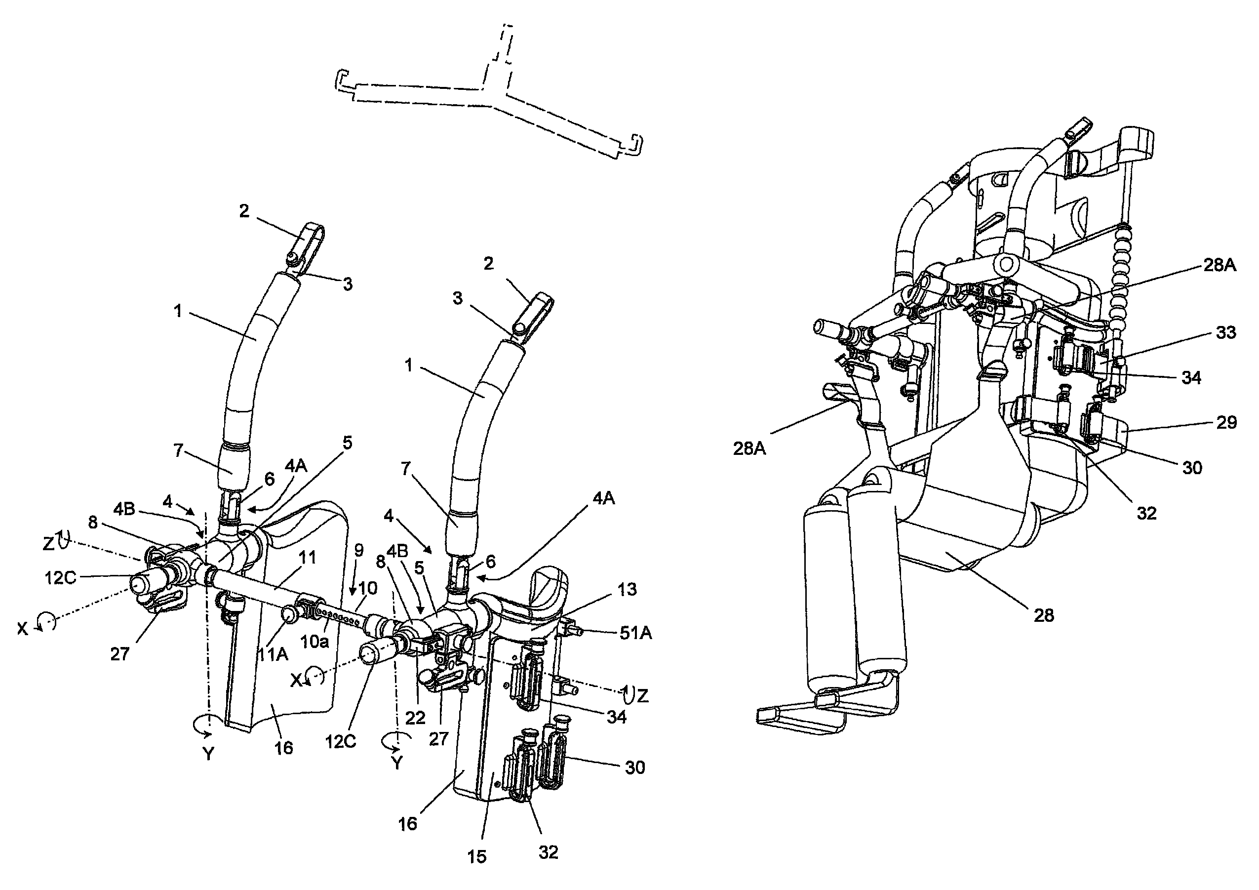
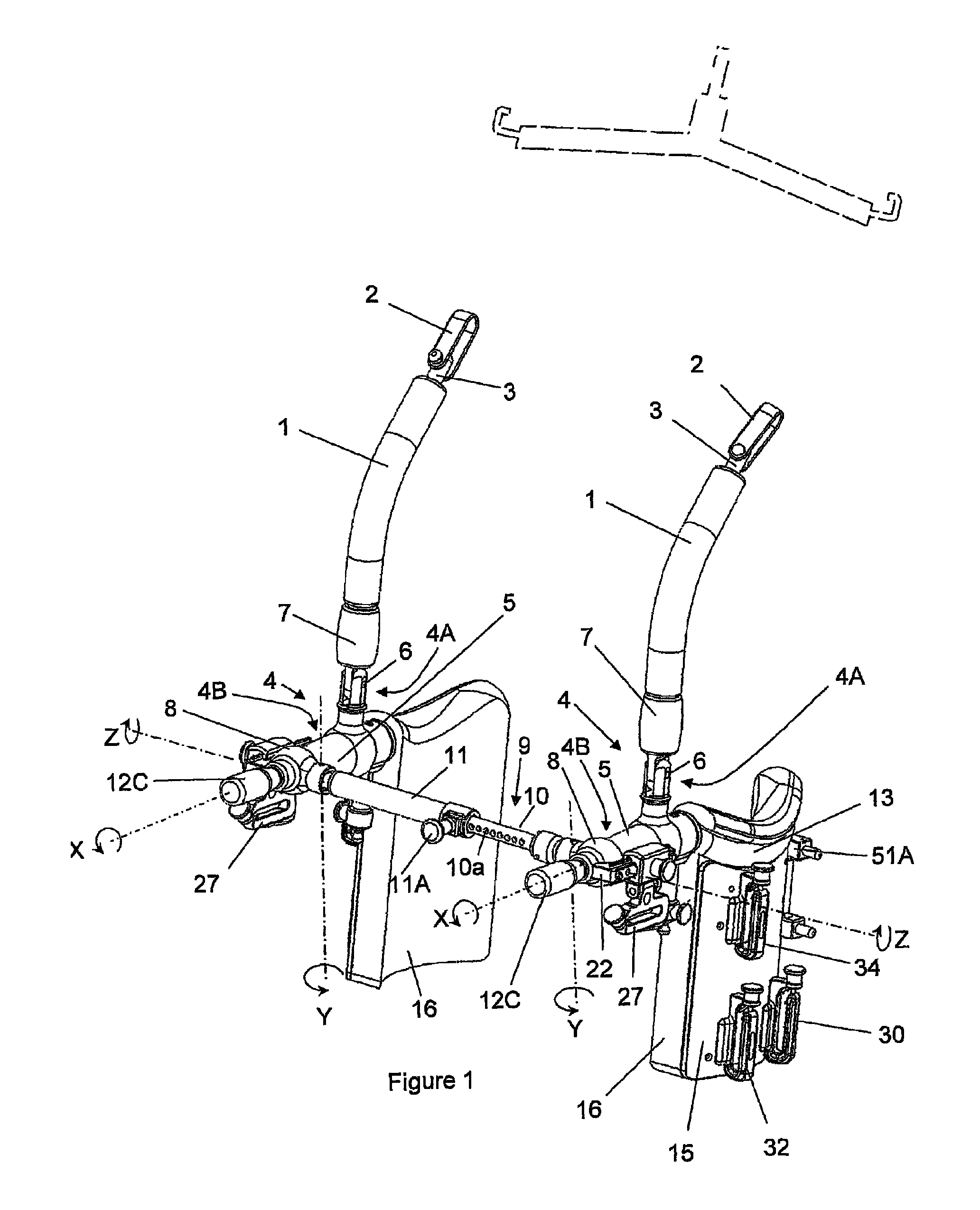
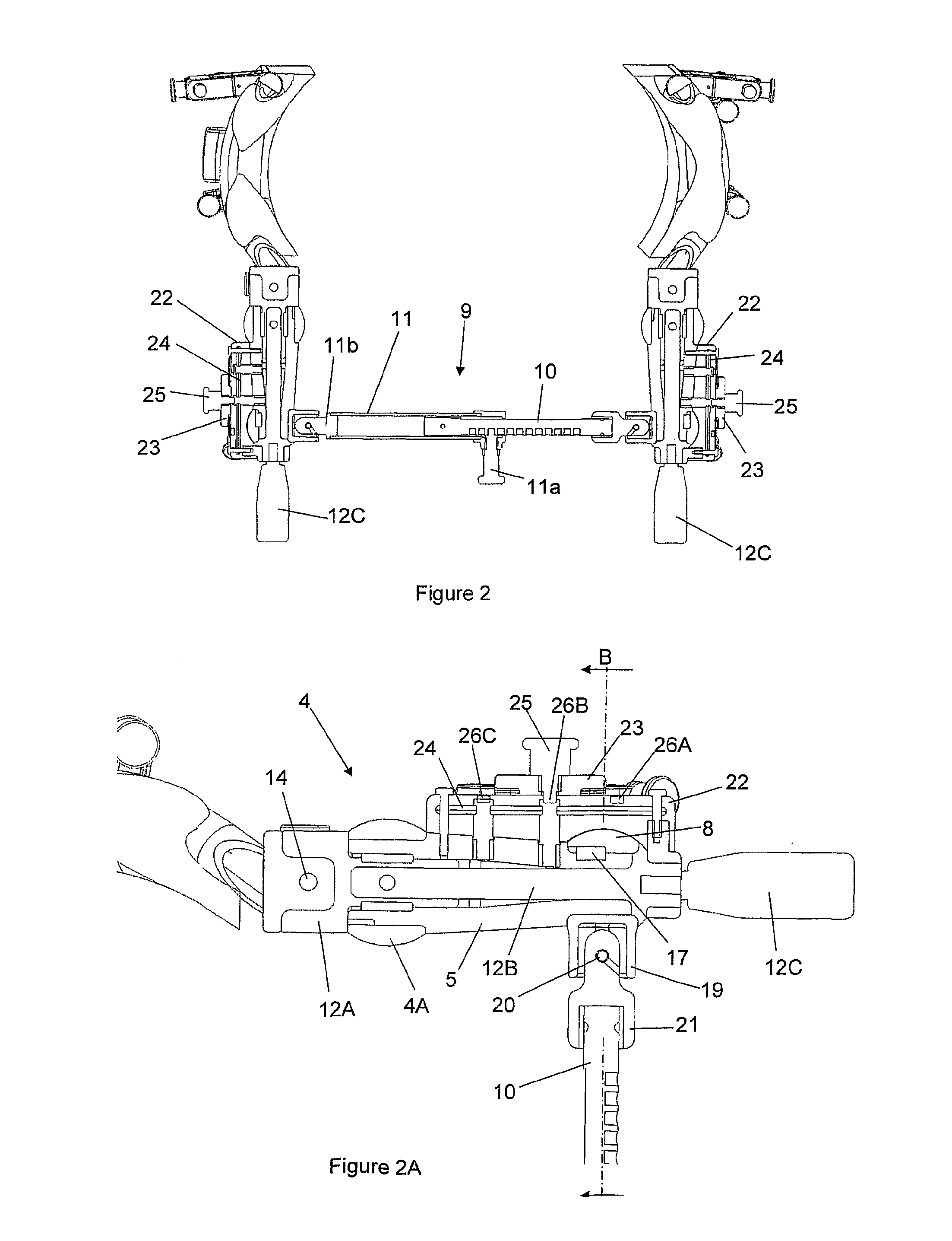
[0065]In the invention as illustrated in FIG. 3A, the boss 5 is rotatably immovable relative to the pivotal / rotary connector 4A but the connecting member 12A is rotatable relative to the boss 5. The axis of rotation defines the second axis of the 2-axis pivotal / rotary connector 4A, and is perpendicular to the axis defined by the pin 6 but offset therefrom. A pin 12D locks together the connecting member 12A and the retaining shaft 12B. A second pin 12E passing down a vertical bore centrally of the bifurcated upper portion of the pivotal / rotary connector 4A and locked in position there by a diagonally inserted grub-screw locks together the boss 5 and the pivotal / rotary connector 4A, keeps the pin 12D securely in place and prevents ingress of dirt. The pin 12E spans the vertical bore in the pivotal / rotary connector 4A and a radial bore in the boss 5, and therefore prevents rotation of the boss 5 relative to the pivotal / rotary connector 4A while permitting rotation of the connecting mem...
second embodiment
[0066]In the invention as illustrated in FIG. 3B, the boss 5 is free to rotate relative to the pivotal / rotary connector 4A. The axis of rotation defines the second axis of the 2-axis pivotal / rotary connector 4A, and is perpendicular to the axis defined by the pin 6 but offset therefrom. A pin 12D′ locks together the boss 5, the connecting member 12A and the retaining shaft 12B. A second pin 12E′ passing down a vertical bore centrally of the bifurcated upper portion of the pivotal / rotary connector 4A and locked in position there by a grub-screw acts both to keep the pin 12D′ securely in place and to prevent ingress of dirt. The pin 12E′ stops short of the boss 5 and therefore does not interfere with rotation of the boss 5 relative to the pivotal / rotary connector 4A.
[0067]The functional difference between the first and second embodiments will be described later.
[0068]The connecting members 12A provide releasable mountings for a pair of patient upper body support means which include pa...
third embodiment
[0078]An alternative seat sling 28′ is shown in FIG. 15A which shows the patient lifting frame, being a modification of the previous Figures. The modification to the frame itself lies in the fact that the rails 22, sliders 23 and carriers 27 of the previous Figures are replaced by a pair of fixed carriers 27′ suspended from the universal joints 8 more or less in line with the Z axis. The carriers 27′ are suspended by mounting frames 27″ from end protrusions 8A formed as integral parts of the universal joints 8 (FIG. 15B), each mounting frame 27″ having a spigot portion received in an upwardly extending bore 8B formed in the associated protrusion 8A and held captive by a pin or bolt inserted in an axial bore 8C. The carriers 27′ thus are fixed in the sense that they are unable to be moved in the forward and back direction, as could the carriers 27 of FIGS. 1 to 15 on their sliders 23. The carriers 27′ can however pivot relative to their mounting frames. The adjustment of the cantilev...
PUM
 Abstract
Description
Claims
Application Information
 - R&D
- Intellectual Property
- Life Sciences
- Materials
- Tech Scout
- Unparalleled Data Quality
- Higher Quality Content
- 60% Fewer Hallucinations
Browse by: Latest US Patents, China's latest patents, Technical Efficacy Thesaurus, Application Domain, Technology Topic, Popular Technical Reports.
© 2025 PatSnap. All rights reserved.Legal|Privacy policy|Modern Slavery Act Transparency Statement|Sitemap|About US| Contact US: help@patsnap.com


