Sensor and display-independent quantitative per-pixel stimulation system

a stimulation system and sensor technology, applied in the field of sensor and display-independent quantitative per-pixel stimulation system, can solve the problems of pilot's experience using the simulator will differ, and the pilot cannot use actual vision-auction equipment during training

Active Publication Date: 2012-06-19
AECHELON TECH
View PDF12 Cites 9 Cited by
  • Summary
  • Abstract
  • Description
  • Claims
  • Application Information

AI Technical Summary

Problems solved by technology

Since the displayed image already incorporates the wavelength translations performed by the sensor—i.e. the system displays simulated images—these types of systems do not allow the pilot to use actual vision-augmenting equipment during training.
This is considered a drawback of simulated systems, because a pilot's experience using the simulator will differ from that during actual flight-for example, wearing NVGs, a pilot may see a sensor-based image occupying most of his field of vision, but may see a regular out-the-window image using his peripheral vision.
The disparity between the simulator and the real world experience is further augmented by the pilot not being able to wear the sensor equipment.

Method used


Image

  • Sensor and display-independent quantitative per-pixel stimulation system
  • Sensor and display-independent quantitative per-pixel stimulation system
  • Sensor and display-independent quantitative per-pixel stimulation system

Examples


Embodiment Construction

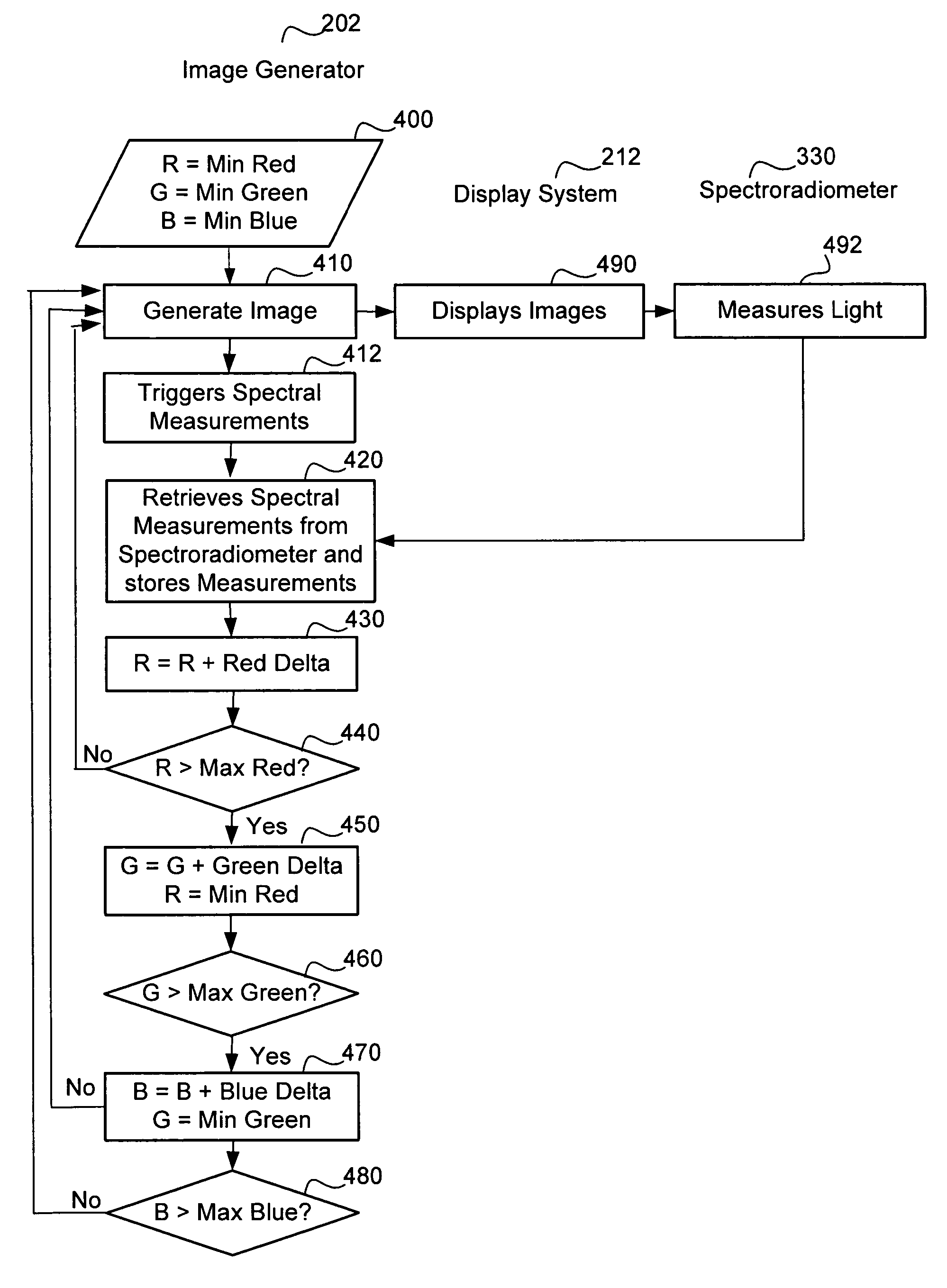
[0019]FIG. 1 illustrates three steps of a method for performing sensor and display-independent sensor stimulation. First, the display system that will be used in conjunction with the sensor is characterized 102 according to the particulars of its emissions. Next, sensor-dependent color lookup tables that map simulated luminance to stimulating color values are created 104. This mapping is specific to the display that has been characterized and to the sensor that will be used with the display. Finally, a simulated image stream is received by the present invention, and using the color lookup tables, for each luminance value provided in the stream, a set of RGB values (or other input values, depending on the display technology involved) is determined 106 that will produce the equivalent stimulated image on the display system. Those color values are then provided to the display system for use with the appropriate sensor. Each of these steps is described further below.
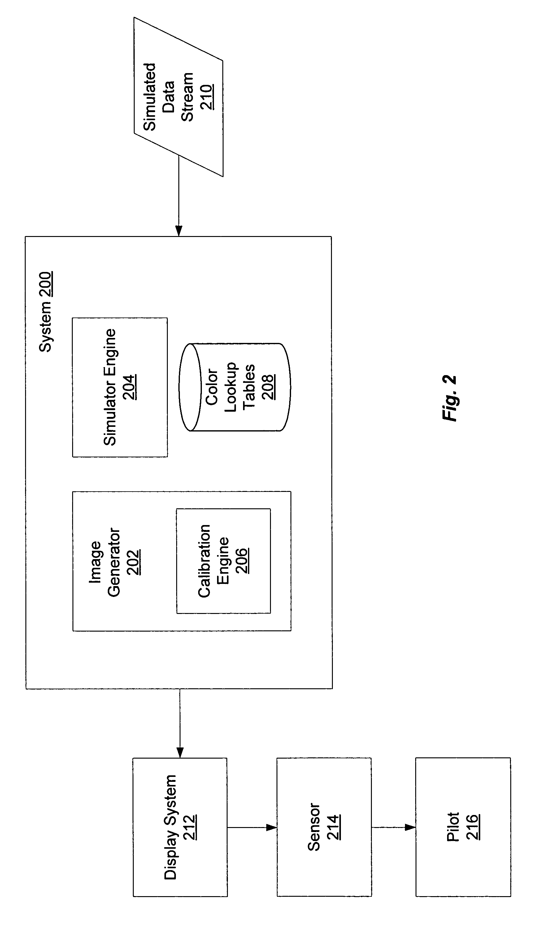
System Architecture

[...


PUM


Abstract

Sensor independent display characterization system spectrally characterizes a display system to measure radiant power emitted by the display system that displays a video image to a trainee pilot during sensor stimulation. A sensor spectral response for each wavelength produced by the stimulated sensor is determined. A stimulated luminance for each color level of the displayed image or for a range of color levels is computed. A color look up table that maps computed stimulated luminance to a set of stimulating color values is generated. When a trainee pilot looks at the displayed image using a sensor having a sensor response that was used in computing the stimulated luminance, the pilot will see an image that was created by simulated spectral rendering. The displayed image is an accurate, display and sensor independent image that the pilot can see during the real flight.

Description

BACKGROUND OF THE INVENTION[0001]1. Field of the Invention[0002]The present invention relates generally to providing computerized simulations of real-world views. In particular, the present invention is directed towards a sensor and display-independent quantitative per-pixel stimulation system.[0003]2. Description of the Related Art[0004]Pilots of aircrafts or other pilot-controlled vehicles sometimes guide their aircraft over a given terrain with the assistance of vision-augmenting equipment known as sensors, including, for example, Night Vision Goggles (NVG's) and Low Level Light Television Cameras (LLLTV's). Sensors typically are used to convert hard-to-see imagery in one or more of the visible and / or invisible spectral bands into imagery that is more clearly visible to the human eye. Sensors often display imagery that is different from the one a pilot may be accustomed to seeing naturally with his or her own eyes (also known as an out-the-window view). Therefore, it is desirable...

Claims


Application Information

Patent Timeline
Patent Type & Authority Patents(United States)
IPC IPC(8): G09G5/00G09B9/08
CPCG09B9/30G09G5/06G06F3/147G09G3/006G09G5/04G09G2320/0242G09G2320/029G09G2360/145G09G2380/12
Inventor CASTELLAR, JAVIERMORGAN, III, DAVID LLOYD
Owner AECHELON TECH
Why Eureka
Try Eureka