
Steam turbine

a steam turbine and steam technology, applied in the direction of machines/engines, liquid fuel engines, lighting and heating apparatus, etc., can solve the problems of affecting the efficiency and the range of application of the steam turbine, affecting the efficiency of the whole system, and affecting the efficiency of the steam turbine. , to achieve the effect of improving the mechanical relationship of the rotor and the stationary casing, improving the stability of the whole system, and improving the efficiency of the steam turbin

Active Publication Date: 2012-06-05
SIEMENS ENERGY GLOBAL GMBH & CO KG
View PDF15 Cites 0 Cited by
  • Summary
  • Abstract
  • Description
  • Claims
  • Application Information

AI Technical Summary

Benefits of technology

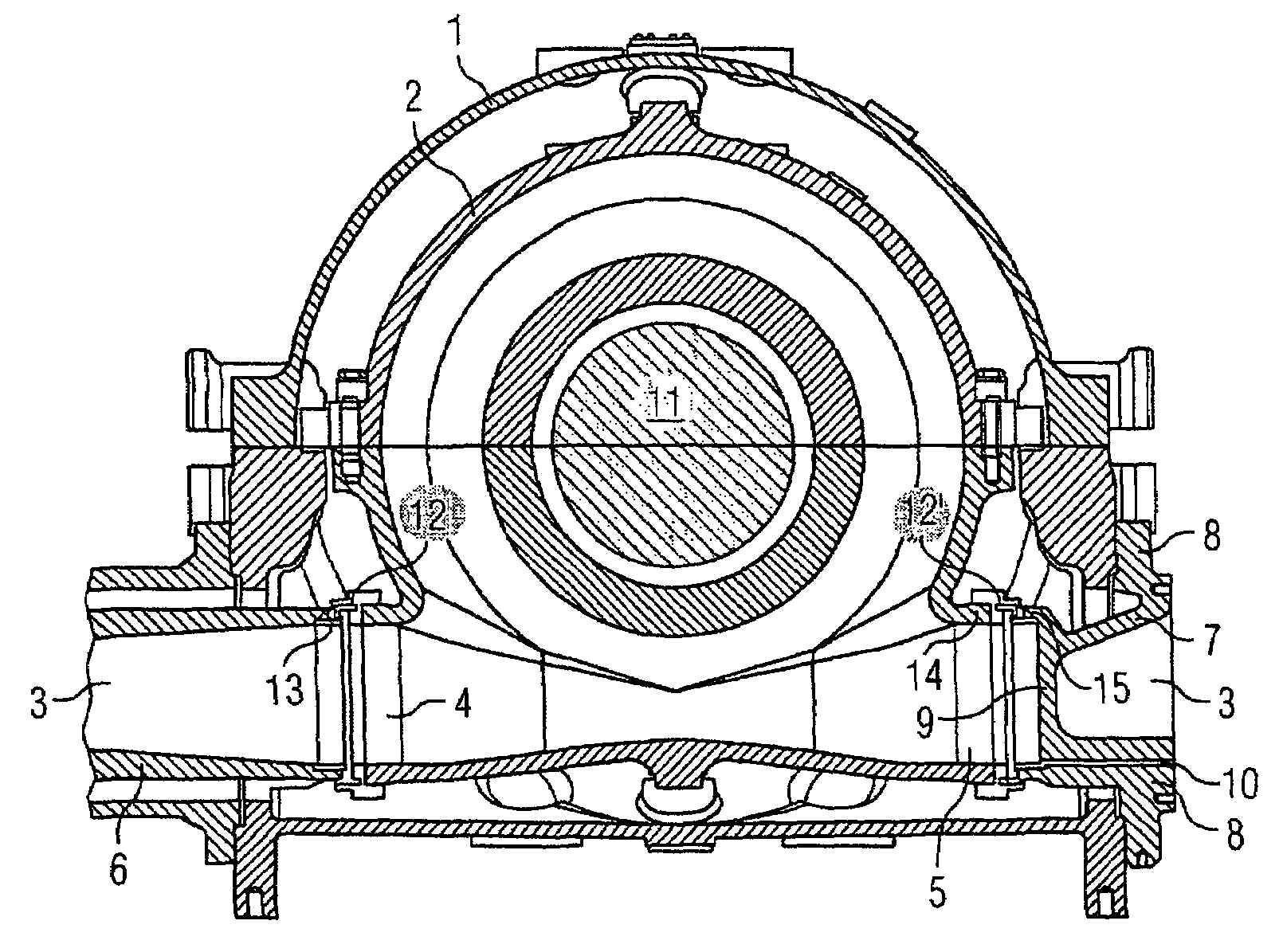
[0008]This object is achieved according to the invention by a steam turbine which is referred to in the introduction, which is characterized in that a pipe for feeding and / or exhausting steam is connectable to a first port opening, and also the second port opening is sealed by a cover. Due to the fact that the port opening which can be provided with the pipe, and the port openings which are sealed by the cover, lie opposite each other in the inner casing, force compensation is brought about in the inner casing during steam inflow through the pipe, similar to when connecting two steam feed pipes to the port openings which lie opposite each other. The occurrence of radial or lateral shear forces is largely prevented as a result. With the steam turbine according to the invention, it is therefore possible to rigidly connect the steam feed pipe to the outer casing, and to design the connection to the inner casing in a flexible manner. Consequently, a simple installation of the steam feed pipe is possible.
[0015]In an expedient embodiment according to the invention, a passage for draining the inner casing and / or outer casing is formed in the cover. As a result, condensate which is formed in the inner casing or outer casing can be discharged from the turbine. Standing condensate which remains in the turbine can lead to asymmetrical structures or casing deformations on account of the varying heat transfer. As a consequence, it can even lead to bridging of clearances in extreme circumstances. Since on account of the immediate expansion of the steam when entering the steam turbine a large amount of condensate accrues at the same time, a discharge passage in this region, i.e. in the cover which is located close to the inlet opening which is connected to the pipe, is especially effective for quick discharge of the condensate. Therefore, asymmetric casing deformations can be avoided and the mechanical relationships of rotor to stationary casing can be improved. In this way, radial clearances in the mechanical design can be minimized, which leads to an increase of efficiency.

Problems solved by technology

In order to compensate radial or lateral shear forces which are caused by thermal expansions and which lead inter alia to undesired deformations or displacements of the inner casing and consequently disadvantageously affect efficiency and range of application of the steam turbine, a pair of port openings, with associated pipes, is provided in the known steam turbines, which port openings are formed opposite each other on the inner casing.
With these known steam turbines, however, the problem arises that feeding steam to the steam turbine via two ports, with a low volumetric flow rate and without corresponding parallel flow at the boiler port, is uneconomical.
The use of a steam turbine with only one port opening is then advisable, but, as previously already explained, leads to the occurrence of large radial or lateral shear forces which disadvantageously affects the efficiency and the range of application of the steam turbine.
This attachment, however, requires a costly installation and leads to a direct transfer of pipe deformations to the inner casing, with the risk of bridging the radial clearances which is associated with these deformations.

Method used


Image

  • Steam turbine
  • Steam turbine

Examples


Embodiment Construction

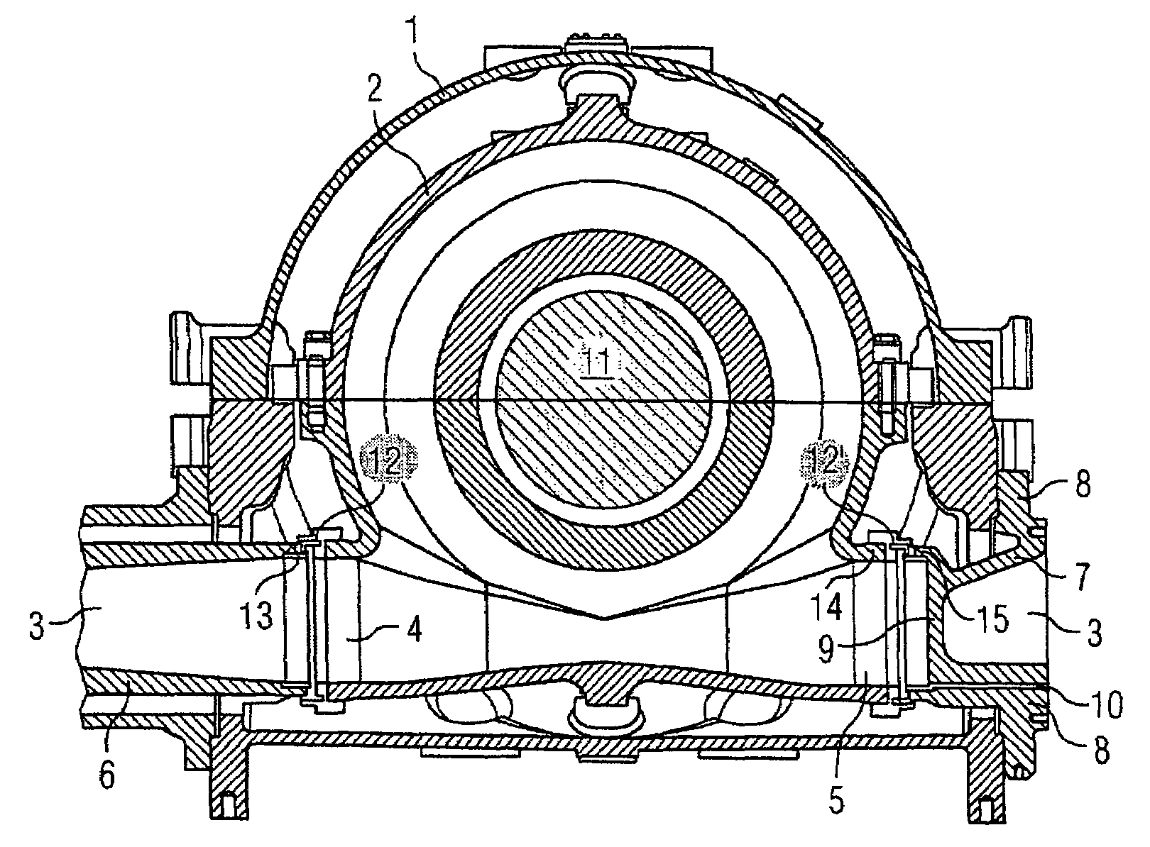
[0019]The FIGURE is a sectional view of a steam turbine according to the invention. In its center, there is a shaft 11 which is enclosed by an inner casing 2. This casing can be axially symmetrically constructed, but does not necessarily have to be symmetrical. An outer casing 1, which can also be axially symmetrically constructed, is arranged around the inner casing 2. Via a steam feed pipe 6, live steam or hot reheated steam, or exhaust steam, can be fed or discharged into or from the inner casing 2 under high pressure. The shaft 11 is driven as a result of the ensuing expansion of the steam which is supplied. Consequently, the expanded steam is guided through the cavity between outer casing 1 and inner casing 2, as a result of which cooling of the inner casing is effected.

[0020]The steam turbine has a port 3 for feeding and / or exhausting steam into or from the inner casing 2, which port is guided through the outer casing 1 both from the left-hand side and from the right-hand side...


PUM


Abstract

A steam turbine has a two-shell housing, including an outer casing and an inner casing arranged therein, as well as a pipe that extends through the outer casing for supplying and / or removing steam to or from the inner casing, the pipe being provided with a pair of apertures arranged opposite each other on the inner casing. According to the invention, a first steam supply or discharge pipe can be connected to a first aperture, and the second aperture is closed by a cover.

Description

CROSS REFERENCE TO RELATED APPLICATIONS[0001]This application is the US National Stage of International Application No. PCT / EP2006 / 060552, filed Mar. 8, 2006 and claims the benefit thereof. The International Application claims the benefits of European application No. 05009709.6 filed May 3, 2005, both of the applications are incorporated by reference herein in their entirety.FIELD OF INVENTION[0002]The invention relates to a steam turbine with a double-shell casing, which comprises an outer casing and an inner casing which is arranged within it, and with a port, which is guided through the outer casing, for feeding and / or exhausting steam into or from the inner casing, wherein the port is designed with a pair of port openings which are formed opposite each other on the inner casing.BACKGROUND OF THE INVENTION[0003]A double-shell construction of casings on steam turbines is preferably used if an expansion of live steam or hot reheated steam is carried out in the steam turbine. In thi...

Claims


Application Information

Patent Timeline
Patent Type & Authority Patents(United States)
IPC IPC(8): F01D21/00F01D5/08
CPCF01D9/06F01D25/26F05D2240/55F05D2230/61F05D2220/31F05D2230/642
Inventor ALMSTEDT, HENNINGESSINK, STEFANSCHWARZ, MARK-ANDRETAMME, RAINERULMA, ANDREASWIEGHARDT, KAI
Owner SIEMENS ENERGY GLOBAL GMBH & CO KG
Learn More